Engineering Chemistry. Module 1, electrochemistry, corrosion and materials.

GXCYT122 · 105 pages · Your place is saved in this browser

Contents · Electrochemistry And Corrosion
Text size18

Page 1 of 105

[Non-content page]


Page 2 of 105

MODULE 1

ELECTROCHEMISTRY AND CORROSION

Electrochemistry

Electro Chemistry deals with the chemical reactions produced by passing electric current through an electrolyte or the production of electric current through chemical reactions.

Differences between Electrochemical cells & Electrolytic cells
Electrochemical cellsElectrolytic cells
A device which converts chemical energy to electrical energyA device which converts electrical energy to chemical energy.
Consists of two electrodes immersed in one or more suitable electrolyte and the electrodes are connected externallyBoth the electrodes are inserted in the same electrolyte solution.
Anode is -ve (LOAN)Anode is +ve
Free energy change (ΔG)(\Delta G) is -ve (Spontaneous)Free energy change (ΔG)(\Delta G) is +ve
Salt bridge is usedSalt bridge is not used.
Eg : Daniel CellEg : Electrolysis

Daniel Cell

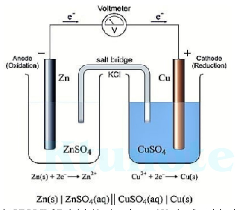
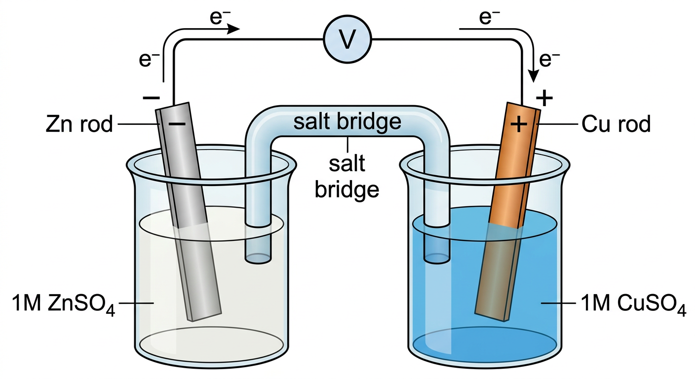
A Daniel cell is the best example of a galvanic cell which converts chemical energy into electrical energy. It consists of two electrodes of dissimilar metals, Zn\text{Zn} and Cu\text{Cu}; each electrode is in contact with a solution of its own ion; Zinc sulphate and copper sulphate respectively.

The Daniel cell can be conventionally represented as Zn/Zn2+∣∣Cu2+/Cu\text{Zn} / \text{Zn}^{2+} || \text{Cu}^{2+} / \text{Cu}

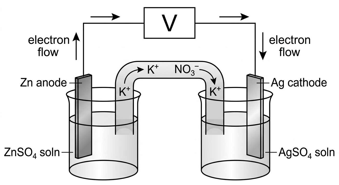
  • In a Daniel cell electrons flow from zinc electrode to copper electrode through an external circuit, while metal ions form one half cell to the other through the salt bridge.
  • Here current flows from copper electrode to zinc electrode that is cathode to anode via an external circuit.
  • Daniel cell is a reversible cell
Cell Reactions

Ion Zn/ZnSO4\text{Zn} / \text{ZnSO}_4 half-cell, oxidation reaction occurs. (anode)

Zn→Zn2++2e−\text{Zn} \rightarrow \text{Zn}^{2+} + 2\text{e}^{-}


Page 3 of 105

Ion Cu/CuSO4\text{Cu/CuSO}_4 half-cell, reduction reaction occurs. (cathode)

Cu2++2e−→Cu\text{Cu}^{2+} + 2\text{e}^- \rightarrow \text{Cu}

The net cell reaction is

Zn+Cu2+⇌Zn2++Cu\text{Zn} + \text{Cu}^{2+} \rightleftharpoons \text{Zn}^{2+} + \text{Cu}

Cell is represented as Zn/Zn2+∥Cu2+/Cu\text{Zn}/\text{Zn}^{2+} \Vert \text{Cu}^{2+}/\text{Cu}

Daniel cell diagram showing zinc anode, copper cathode, salt bridge, and voltmeter

Zn(s)∣ZnSO4(aq)∥CuSO4(aq)∣Cu(s)\text{Zn(s)} \mid \text{ZnSO}_4(\text{aq}) \Vert \text{CuSO}_4(\text{aq}) \mid \text{Cu(s)}

SALT BRIDGE: Salt bridge is an inverted U tube. Containing inert electrolytes salts like KCl\text{KCl} or NH4NO3\text{NH}_4\text{NO}_3 in agar-agar or gelatine. The ions of K+\text{K}^+ and Cl−\text{Cl}^- have equal mobility.

Functions of Salt bridge

  • A salt bridge maintains the electrical neutrality of each half cells.
  • It prevents the accumulation of charges.
  • Salt bridge also prevents the diffusion of interfering ions from one compartment to another.
  • A salt bridge minimizes or eliminates the liquid junction potential.
  • Salts like KCl\text{KCl}, NH4NO3\text{NH}_4\text{NO}_3 are used for making salt bridge. Ions like K+\text{K}^+ and Cl−\text{Cl}^- has equal mobility and get drifted to cathode and anode compartments respectively under the potential difference.

Single Electrode Potential

It is measure of tendency of an electrode to lose or gain electron. Tendency of electrode for


Page 4 of 105

oxidation (loose electrons) is oxidation potential and tendency for reduction (gain electrons) is reduction potential EredE_{\text{red}}. Ered=−EoxdE_{\text{red}} = - E_{\text{oxd}}

Factors affecting electrode potential

  1. Concentration of metal irons in the solution
  2. Temperature of the solution
  3. Nature of the metal

REVERSIBLE AND IRREVERSIBLE CELLS

A cell is said to be reversible if it satisfies the following conditions, _______

  1. If an emf exactly equal to that of a cell is applied the chemical reaction taking place in the cell will stops

  2. If the external emf is slightly greater than the actual emf of the cell applied, the cell reaction gets reversed.

Eg : Daniel cell

If a cell does not obey the following conditions it is said to be irreversible. Eg : Dry cell

NERNST EQUATION

The relation between the electrode potential and the concentration of the electrolyte solution is given by Nernst equation.

Walter Nernst derived a mathematical relationship which enables us to calculate the effect of electrolyte concentration on electrode potential.

For a half cell,

E=E0−2.303RTnFlog⁡1[Mn+]E = E^0 - \frac{2.303RT}{nF} \log \frac{1}{[M^{n+}]}

E=E0−0.0591nlog⁡1[Mn+] at 25∘CE = E^0 - \frac{0.0591}{n} \log \frac{1}{[M^{n+}]} \text{ at } 25^\circ\text{C}

where, E0E^0=Standard electrode potential RR=gas constant; TT= temperature in KK nn=number of electrons transferred in the half cell reaction; FF=faraday of electricity; [Mn+]=[M^{n+}]= concentration of electrolyte.

DERIVATION

Nernst equation gives us the effect of electrolyte concentration on electrode potential.

Consider a general reduction reaction, taking place at the electrode Mn++ne−→MM^{n+} + ne^- \rightarrow M

The decrease in free energy, ΔG\Delta G accompanying this process is given by the well-known thermodynamic equation (Vant Hoff's equation)

ΔG=ΔG0+RTln⁡Q…(1)\Delta G = \Delta G^0 + RT \ln Q \dots \text{(1)}

R=gas constant ,Q is the reaction quotient=Conc of Products/conc of reactant [P]/[R]R = \text{gas constant } , Q \text{ is the reaction quotient} = \text{Conc of Products} / \text{conc of reactant } [P]/[R]


Page 5 of 105

In a reversible cell, electrical energy is produced at the expense of decrease in free energy, and free energy is related with EMF of the cell as follows

ΔG=−nFE,ΔG0=−nFE0\Delta \text{G} = -n\text{FE}, \quad \Delta \text{G}^0 = -n\text{FE}^0

Substitute in (1) −nFE=−nFE0+RTln⁡Q-n\text{FE} = -n\text{FE}^0 + \text{RT} \ln \text{Q}

Dividing by −nF-n\text{F}

E=E0−RT/nF ln Q … (2)\text{E} = \text{E}^0 - \text{RT} / n\text{F} \text{ ln Q } \dots \text{ (2)}

Substituting the values of constants at the temperature T=298 K\text{T} = 298\text{ K}, R=8.314JK−1 mol−1\text{R} = 8.314 \text{JK}^{-1}\text{ mol}^{-1}, F=96500C\text{F} = 96500\text{C}, Q=[M]/[Mn+]\text{Q} = [\text{M}] / [\text{M}^{n+}] and converting in to natural log

E=E0−2.303RT/nFlog⁡[M]/[Mn+]\text{E} = \text{E}^0 - 2.303\text{RT}/n\text{F} \log [\text{M}] / [\text{M}^{n+}]

Pure solid [M][\text{M}] is taken as one E=E0−2.303RT/nFlog⁡1/[Mn+]\text{E} = \text{E}^0 - 2.303\text{RT}/ n\text{F} \log 1 / [\text{M}^{n+}]

This equation is called Nernst equation. It's clear that electrode potential is directly proportional to molar concentration of ions in the same solution and temperature.

Nernst Equation for a complete cell

For a cell reaction a A+b B⟶c C+d D\text{a A} + \text{b B} \longrightarrow \text{c C} + \text{d D} The reaction quotient Q\text{Q} can be written as Q\text{Q}

=[C]c[D]d/[A]a[B]b= [\text{C}]^c[\text{D}]^d / [\text{A}]^a[\text{B}]^b

Thus the Nernst equation for a complete cell is given by

Ecell=Ecell0−0.0591/nlog⁡Q\text{E}_{\text{cell}} = \text{E}^0_{\text{cell}} - 0.0591/n \log \text{Q}

Ecell=Ecell0−0.0591/nlog⁡[C]c[D]d/[A]a[B]b\text{E}_{\text{cell}} = \text{E}^0_{\text{cell}} - 0.0591/n \log [\text{C}]^c[\text{D}]^d / [\text{A}]^a[\text{B}]^b

For a Daniel cell , Cu2++Zn⟶Zn2++Cu\text{Cu}^{2+} + \text{Zn} \longrightarrow \text{Zn}^{2+} + \text{Cu} Q=[Zn2+][Cu]/[Cu2+][Zn]\text{Q} = [\text{Zn}^{2+}] [\text{Cu}] / [\text{Cu}^{2+}][\text{Zn}]

Ecell=Ecell0\text{E}_{\text{cell}} = \text{E}^0_{\text{cell}}

−0.0591/nlog⁡Q- 0.0591/n \log \text{Q}

Here concentration of pure solids are taken as one then,

Q=[Zn2+]/[Cu2+]Ecell=Ecell0−2.303RT/nFlog⁡[Zn2+]/[Cu2+]\text{Q} = [\text{Zn}^{2+}] / [\text{Cu}^{2+}] \quad \text{E}_{\text{cell}} = \text{E}^0_{\text{cell}} - 2.303\text{RT}/n\text{F} \log [\text{Zn}^{2+}] / [\text{Cu}^{2+}]

Ecell=Ecell0−0.0591/nlog⁡[Zn2+]/[Cu2+]\text{E}_{\text{cell}} = \text{E}^0_{\text{cell}} - 0.0591/n \log [\text{Zn}^{2+}] / [\text{Cu}^{2+}]

free energy and EMF: The cell in a reversible cell, electrical energy is produced at the expense of decrease in free energy ΔG\Delta \text{G},

Electrical energy produced per mol=nFE= n\text{FE}

ΔG=−nFE\Delta \text{G} = -n\text{FE} where F is called Faraday which is the charge of one mole of electrons. (F=6.023×1023×1.6×10−19=96500 C\text{F} = 6.023 \times 10^{23} \times 1.6 \times 10^{-19} = 96500\text{ C}); n\text{n} is number of electrons; E\text{E} is EMF\text{EMF}

Variation of EMF of Hydrogen Electrode with pH of a solution


Page 6 of 105

For a Hydrogen Electrode at 25∘C25^\circ\text{C} H++1e→12 H2\text{H}^+ + 1\text{e} \xrightarrow{\hspace*{1.5cm}} \frac{1}{2}\text{ H}_2

Nernst equation can be written as,

E=E0+0.0591/nlog⁡ [H+]E = E^0 + 0.0591/n \log\ [\text{H}^+] pH=−log⁡[H+]\text{pH} = -\log[\text{H}^+]

E=−0.0591pH\mathbf{E = - 0.0591pH}

Case 1: When pH=0\mathbf{\text{pH} = 0} i.e. E=−0.0591∗0=0 V\mathbf{E = -0.0591*0 = 0\text{ V}} (acidic condition)

Case 2: When pH=7\mathbf{\text{pH} = 7} i.e. E=−0.0591∗7=−0.414V\mathbf{E = - 0.0591*7 = - 0.414\text{V}} (Neutral)

Case 3: When pH=14\mathbf{\text{pH} = 14} i.e. E=−0.0591∗14=−0.825 V\mathbf{E = -0.0591*14 = -0.825\text{ V}} (Alkaline)

Variation of EMF of Oxygen Electrode with pH of a solution

For oxygen electrode at 25∘C25^\circ\text{C} O2+4H++4e→2 H2O\text{O}_2 + 4\text{H}^+ + 4\text{e} \xrightarrow{\hspace*{1.5cm}} 2\text{ H}_2\text{O} Nernst equation can be written as,

E=E0+0.0591/nlog⁡ [H+]4E = E^0 + 0.0591/n \log\ [\text{H}^+]^4 n=4n=4 E0=1.23VE^0 = 1.23\text{V}

E=E0+0.0591/4log⁡ [H+]∗4E = E^0 + 0.0591/4 \log\ [\text{H}^+]^*4

E=1.23−0.0591log⁡ pHE = 1.23 - 0.0591 \log\text{ pH}

Case 1: When pH=0\mathbf{\text{pH} = 0} i.e. E=1.23−0.0591∗0=1.23V\mathbf{E = 1.23 - 0.0591*0 = 1.23\text{V}}

Case 2: When pH=7\mathbf{\text{pH} = 7} i.e. E=1,23−0.0591∗7=0.81V\mathbf{E = 1,23 - 0.0591*7 = 0.81\text{V}}

Case 3: When pH=14\mathbf{\text{pH} = 14} i.e. E=1.23−0.0591∗14=0.40V\mathbf{E = 1.23 - 0.0591*14 = 0.40\text{V}}

Applications of Nernst equation

  1. To study the effect of electrolyte concentration on electrode potential.
  2. Calculation of equilibrium constant of a reaction.

At equilibrium, anodic and cathodic reactions become equal. So EcellE_{\text{cell}} become 0.

So the Nernst equation is, Ecell=Ecell0−0.0591/nlog⁡ QE_{\text{cell}} = E^0_{\text{cell}} - 0.0591/n \log\text{ Q} ( at equilibrium Q= K the equilibrium constant)

So at equilibrium , 0=Ecell0−0.0591/nlog⁡ K\mathbf{0 = E^0_{\text{cell}} - 0.0591/n \log\text{ K}}, Ecell0=(0.0591/n)log⁡ K\mathbf{E^0_{\text{cell}} = (0.0591/n) \log\text{ K}} Log K=n Ecell00.0591\mathbf{\text{Log K} = \frac{n\text{ E}^0_{\text{cell}}}{0.0591}}

  1. Determination of EMF of a Cell

  2. Determination of unknown concentration.

  3. Determination of a p H of a solution.

  4. Used for finding out valency of an ion

NUMERICALS

  1. The standard electrode potential of zinc ions is 0.76V0.76\text{V}. What will be the potential of a 2M2\text{M} solution at 300K300\text{K}?

Page 7 of 105

The Nernst equation for the given conditions can be written as follows;

EMn+/M=E∘+[(2.303RT)/nF]×log⁡[Mn+]E_{M^{n+}/M} = E^\circ + [(2.303RT)/nF] \times \log [\text{Mn}^+]

Here, E∘=0.76VE^\circ = 0.76\text{V} n=2n = 2 F=96500 C/moleF = 96500\text{ C/mole} [Mn+]=2 M[\text{Mn}^+] = 2\text{ M} R=8.314 J/K moleR = 8.314\text{ J/K mole} T=300 KT = 300\text{ K}

Substituting the given values in Nernst equation we get,

EZn2+/Zn=0.76+[(2.303×8.314×300)/(2×96500)]×log⁡2=0.76+[0.0298×(0.301)]=0.76+0.009=0.769VE_{\text{Zn}^{2+}/\text{Zn}} = 0.76 + [(2.303 \times 8.314 \times 300)/(2 \times 96500)] \times \log 2 = 0.76 + [0.0298 \times (0.301)] = 0.76 + 0.009 = \mathbf{0.769V}

Therefore, the potential of a 2M2\text{M} solution at 300K300\text{K} is 0.769V0.769\text{V}.

  1. What is the Cell Potential of the electrochemical cell in which the cell reaction is: Pb2++Cd⟶Pb+Cd2+\text{Pb}^{2+} + \text{Cd} \longrightarrow \text{Pb} + \text{Cd}^{2+}; Given that Ecell∘=0.277 voltsE^\circ_{\text{cell}} = 0.277\text{ volts}, temperature=25∘C\text{temperature} = 25^\circ\text{C}, [Cd2+]=0.02M[\text{Cd}^{2+}] = 0.02\text{M}, and [Pb2+]=0.2M[\text{Pb}^{2+}] = 0.2\text{M}.

Since the temperature is equal to 25∘C25^\circ\text{C}, the Nernst equation can be written as follows;

Ecell=Ecell∘−(0.0592/n)log⁡10QE_{\text{cell}} = E^\circ_{\text{cell}} - (0.0592/n) \log_{10}Q

Here, two moles of electrons are transferred in the reaction. Therefore, n=2n = 2. The reaction quotient (QQ) is given by [Cd2+]/[Pb2+]=(0.02M)/(0.2M)=0.1[\text{Cd}^{2+}]/[\text{Pb}^{2+}] = (0.02\text{M})/(0.2\text{M}) = 0.1.

The equation can now be rewritten as:

Ecell=0.277−(0.0592/2)×log⁡10(0.1)=0.277−(0.0296)(−1)=0.3066 VoltsE_{\text{cell}} = 0.277 - (0.0592/2) \times \log_{10}(0.1) = 0.277 - (0.0296)(-1) = \mathbf{0.3066\text{ Volts}} Thus, the cell potential of this electrochemical cell at a temperature of 25∘C25^\circ\text{C} is 0.3066 volts0.3066\text{ volts}.

  1. The Cu2+ion\text{Cu}^{2+}\text{ion} concentration in a copper-silver electrochemical cell is 0.1M0.1\text{M}. If E∘(Ag+/Ag)=0.8VE^\circ(\text{Ag}^+/\text{Ag}) = 0.8\text{V}, E∘(Cu2+/Cu)=0.34VE^\circ(\text{Cu}^{2+}/\text{Cu}) = 0.34\text{V}, and Cell potential (at 25∘C25^\circ\text{C}) = 0.422V0.422\text{V}, find the silver ion concentration.

Here, the silver electrode acts as a cathode whereas the copper electrode serves as the anode. This is because the standard electrode potential of the silver electrode is greater than that of the copper electrode. The standard electrode potential of the cell can now be calculated, as shown below.

Ecell∘=Ecathode∘−Eanode∘=0.8V−0.34V=0.46VE^\circ_{\text{cell}} = E^\circ_{\text{cathode}} - E^\circ_{\text{anode}} = 0.8\text{V} - 0.34\text{V} = 0.46\text{V}

Since the charge on the copper ion is +2+2 and the charge on the silver ion is +1+1, the balanced cell reaction is:

Cu⟶Cu2++2e\text{Cu} \longrightarrow \text{Cu}^{2+} + 2\text{e}

2Ag++2e⟶2Ag2\text{Ag}^+ + 2\text{e} \longrightarrow 2\text{Ag}

2Ag++Cu⟶2Ag+Cu2+2\text{Ag}^+ + \text{Cu} \longrightarrow 2\text{Ag} + \text{Cu}^{2+}

Since two electrons are transferred in the cell reaction, n=2n = 2. Now, the Nernst equation for this electrochemical cell can be written as follows.

Ecell=Ecell∘−(0.0592/2)×log⁡(0.1/[Ag+]2)E_{\text{cell}} = E^\circ_{\text{cell}} - (0.0592/2) \times \log (0.1/[\text{Ag}^+]^2)

0.422V=0.46−0.0296×(−1−2log⁡[Ag+])0.422\text{V} = 0.46 - 0.0296 \times (-1 - 2\log [\text{Ag}^+])

Therefore, −2log⁡[Ag+]=1.283+1=2.283-2\log [\text{Ag}^+] = 1.283 + 1 = 2.283

Or, log⁡[Ag+]=−1.141\log [\text{Ag}^+] = -1.141


Page 8 of 105

[Ag+]=antilog (−1.141)=0.0722 M[\text{Ag}^+] = \text{antilog } (-1.141) = 0.0722 \text{ M}

  1. Find the cell potential of a galvanic cell based on the following reduction half-reactions at 25 ∙C25\text{ }^\bullet\text{C}
    Cd2++2 e−→Cd E0=−0.403 V\text{Cd}^{2+} + 2\text{ e}^- \rightarrow \text{Cd } E^0 = -0.403 \text{ V}
    Pb2++2 e−→Pb E0=−0.126 V\text{Pb}^{2+} + 2\text{ e}^- \rightarrow \text{Pb } E^0 = -0.126 \text{ V}
    where [Cd2+]=0.020 M[\text{Cd}^{2+}] = 0.020 \text{ M} and [Pb2+]=0.200 M[\text{Pb}^{2+}] = 0.200 \text{ M}.

  2. Calculate the emf of the cell. Zn∣Zn2+(0.001M)∣∣Cu2+(0.1M)∣Cu\text{Zn}|\text{Zn}^{2+}(0.001\text{M})||\text{Cu}^{2+}(0.1\text{M})|\text{Cu} The standard potential of Cu/Cu2+\text{Cu}/\text{Cu}^{2+} half-cell is +0.34+0.34 and Zn/Zn2+\text{Zn}/\text{Zn}^{2+} is −0.76 V-0.76\text{ V}.

Given Zn∣Zn2+(0.001M)∣∣Cu2+(0.1M)∣Cu\text{Zn}|\text{Zn}^{2+}(0.001\text{M})||\text{Cu}^{2+}(0.1\text{M})|\text{Cu}
Overall cell reaction:
Zn→Zn2++2e−\text{Zn} \rightarrow \text{Zn}^{2+} + 2\text{e}^-
Cu2++2e−→Cu\text{Cu}^{2+} + 2\text{e}^- \rightarrow \text{Cu}
Zn+Cu2+→Zn2++Cu\text{Zn} + \text{Cu}^{2+} \rightarrow \text{Zn}^{2+} + \text{Cu}
Ecell0=standard reduction potential of cathode−standard oxidation potential of anodeE^0_{\text{cell}}=\text{standard reduction potential of cathode} - \text{standard oxidation potential of anode}
Ecell0=0.34+0.76 VE^0_{\text{cell}} = 0.34 + 0.76 \text{ V}
Ecell0=1.1 VE^0_{\text{cell}} = 1.1 \text{ V}

Kc=[Cu2+]/[Zn2+]=10−1/10−3=102K_c=[\text{Cu}^{2+}]/[\text{Zn}^{2+}]=10^{-1}/10^{-3}=10^2
EMF of the cell at any electrode concentration is:
E=E0−0.059/n log (Kc)=1.1−0.0295log(102)=1.1−0.0295×(2)=1.1−0.059=1.041 VE=E^0-0.059/n \text{ log } (K_c)=1.1-0.0295\text{log}(10^2)=1.1-0.0295\times(2)=1.1-0.059=1.041\text{ V}

  1. What will be the standard electrode potential of Ni2+/Ni\text{Ni}^{2+} / \text{Ni} electrode if the cell potential of the cell

Ni/Ni 2+(0.1M)//Cu2+(0.01M)/Cu\text{Ni} / \text{Ni } 2+ (0.1\text{M}) // \text{Cu}^{2+}(0.01\text{M}) / \text{Cu} is 0.59 V0.59 \text{ V} at 25oC25\text{o}\text{C}? E0 Cu 2+/Cu=0.34 VE^0\text{ Cu } 2+/\text{Cu} = 0.34 \text{ V}. E cell=Ecell0−(0.0591/n) log [Ni 2+]/[Cu2+]E\text{ cell} = E^0_{\text{cell}} - (0.0591/n) \text{ log } [\text{Ni } 2+] / [\text{Cu}^{2+}]

0.59=Ecell0−(0.0591/2) log 0.1/0.01,Ecell0=0.59+0.02955=0.61955 V0.59 = E^0_{\text{cell}} - (0.0591/2) \text{ log } 0.1 / 0.01, E^0_{\text{cell}} = 0.59 + 0.02955 = 0.61955 \text{ V}

Ecell0=Ecathode0−Eanode0 Ecell0=ECu2+/Cu0−ENi2+/Ni0E^0_{\text{cell}} = E^0_{\text{cathode}} - E^0_{\text{anode}} \text{ } E^0_{\text{cell}} = E^0_{\text{Cu}^{2+}/\text{Cu}} - E^0_{\text{Ni}^{2+}/\text{Ni}}

0.61955=+0.34−ENi2+/Ni00.61955 = +0.34 - E^0_{\text{Ni}^{2+}/\text{Ni}}

ENi2+/Ni0=−0.27955 VE^0_{\text{Ni}^{2+}/\text{Ni}} = -0.27955 \text{ V}

At anode Ni (s)→Ni2++2e\text{Ni (s)} \rightarrow \text{Ni}^{2+} + 2\text{e}
At cathode Cu2++2e→Cu(s)\text{Cu}^{2+} + 2\text{e} \rightarrow \text{Cu(s)}

Electrochemical Series

A series which represents an arrangement of various metal electrodes in the increasing order of their standard reduction potentials or decreasing order of oxidation potential is called electrochemical series.

Li, K, Na, Mg, Al, Zn, Fe, Ni, H2, Ag, Hg, Cu, Au, F\text{Li, K, Na, Mg, Al, Zn, Fe, Ni, H}_2\text{, Ag, Hg, Cu, Au, F} (Increasing order of reduction potential)

Applications of Electrochemical Series
  1. Reactivity of Metals:

Electrodes having negative values of standard electrode potential with respect to hydrogen


Page 9 of 105

have tendency to undergo oxidation and act as anode. whereas electrodes having positive values have tendency to undergo reduction and act as cathode in aqueous solution.

  1. Displacement reaction:

a) To predict whether a given metal will displace another from its salt solution.

Metals having lower reduction potential will always displace metals having higher reduction potential.

E.g.: Zn\text{Zn} metal can displace Cu\text{Cu} from CuSO4\text{CuSO}_4

b) Metals having negative electrode potentials can displace hydrogen gas from acids.

e.g.: Metals like Fe, Zn, Al\text{Fe, Zn, Al} etc. Can liberate H2\text{H}_2 gas when react with acids.

  1. Spontaneity of a redox reaction:

The emf of the cell is positive, the cell reaction is spontaneous. If emf of a cell is negative, the reaction will not occur at all.

  1. Calculation of EMF of a cell:

EMF of the cell can be readily calculated from the relation

Ecell=ER0−EL0E_{\text{cell}} = E^0_{\text{R}} - E^0_{\text{L}}

  1. Predicting the anode and cathode: The electrode with higher reduction potential will act as cathode and the electrode having lower electrode potential will act as anode

  2. Prediction of relative oxidising and reducing tendency.

  3. Corrosion:

The metal higher in the series is anodic or more active and they are more prone to corrosion. The metals lower in the series are noble metals and they are less prone to corrosion.

  1. Predicting the Product of Electrolysis:

Problems

  1. Write the product of electrolysis when we electrolyse the acidified mixture of NaCl\text{NaCl} and KI\text{KI} in aqueous solution? Given that ECl2/Cl−0=1.36 VE^0_{\text{Cl}_2/\text{Cl}^-} = 1.36\text{ V} EI2/I−0=0.54 VE^0_{\text{I}_2/\text{I}^-} = 0.54\text{ V} EK+/K−0=−2.93 VE^0_{\text{K}^+/\text{K}^-} = -2.93\text{ V} ENa+/Na0=−2.71E^0_{\text{Na}^+/\text{Na}} = -2.71

During electrolysis the cell behaves like an electrolytic cell. So anode is positive

The ions going to anode are Cl−,I−\text{Cl}^-, \text{I}^- From electrochemical series the electrode potential of I−\text{I}^- is less than the electrode potential of Cl\text{Cl} so I−\text{I}^- goes to anode and the reaction is

At anode (Oxidation) 2I−⟶I2+2e−2\text{I}^- \longrightarrow \text{I}_2 + 2\text{e}^-

Cathode is positive and the ions goes to cathode are H+,Na+\text{H}^+, \text{Na}^+ & K+\text{K}^+ The electrode potential of H+\text{H}^+ is higher than Na+\text{Na}^+ & K+\text{K}^+ the H+\text{H}^+ goes in to cathode.


Page 10 of 105

At Cathode (Reduction) 2H++2e−⟶H22\text{H}^+ + 2\text{e}^- \longrightarrow \text{H}_2

REFERENCE ELECTRODES

A reference electrode is an electrode which has a stable electrode potential with which we can compare the electrode potential of other electrodes.

Reference electrodes are of two types. Primary reference electrode and secondary reference electrode.

Primary reference electrode: Electrodes whose electrode potential is taken as zero at all temperatures. Eg: Standard Hydrogen Electrode (SHE)

Standard Hydrogen Electrode (SHE)

The standard hydrogen electrode is a gas electrode, used as primary reference electrode.. Its electrode potential is taken as 00.

Construction:

  • It is a primary reference electrode.
  • A small Pt\text{Pt} plate coated with Pt\text{Pt} black is connected to a Pt\text{Pt} wire which is sealed in a glass jacket.
  • Glass jacket having an inlet for Hydrogen gas (at 1atm1\text{atm} pressure and 298K298\text{K}) and a number of small holes at the bottom for the escape of Hydrogen gas
  • It is dipped in 1M HCl1\text{M } \text{HCl} solution at 298K298\text{K}.
Working
  • SHE is a reversible electrode which can act as cathode or anode, depending on the potential of electrode to which it is coupled. If it act as anode the electrode can be represented as, The electrode can be represented as Pt,H2 (g)1atm/H+ (1M)\text{Pt}, \text{H}_2\text{ (g)} 1\text{atm} / \text{H}^+\text{ (1M)} If it act as cathode the electrode can be represented as, H+ (1M)/H2 (g)1atm,Pt\text{H}^+\text{ (1M)} / \text{H}_2\text{ (g)} 1\text{atm}, \text{Pt}

  • At the cathode, 2H++2e−⟶H2 (g)2\text{H}^+ + 2\text{e}^- \longrightarrow \text{H}_2\text{ (g)} (reduction), If the potential of coupled electrode is less than zero (Eg: Zn, Mg\text{Zn, Mg})

  • At the anode, H2(g)⟶2H++2e−\text{H}_2\text{(g)} \longrightarrow 2\text{H}^+ + 2\text{e}^- (oxidation) If the potential of coupled electrode is greater than zero (Eg: CU, Ag\text{CU, Ag})

Limitations

  • It is readily affected by compounds of Hg, As\text{Hg, As} and S\text{S} and it cannot be used in

Page 11 of 105

solution Containing these ions.

  • It cannot be used in presence of strong oxidizing and reducing agents.
  • It is expensive due to Pt.
  • The Pt surface must be specially prepared and maintained or it is difficult to maintain Pt surface.
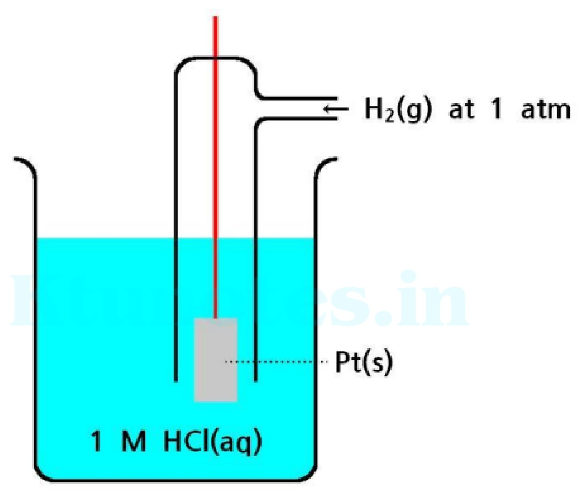
Standard Hydrogen Electrode (SHE) setup diagram

Applications

  • Used as a reference electrode for increasing the electrode potential of other electrodes.
  • Used in the determination of pH
  • it can be used over the entire pH range

Secondary reference electrode: Electrodes with known or constant electrode potential

E.g.: Calomel electrode, glass electrode, quinhydrone electrode

CALOMEL ELECTRODE


Page 12 of 105

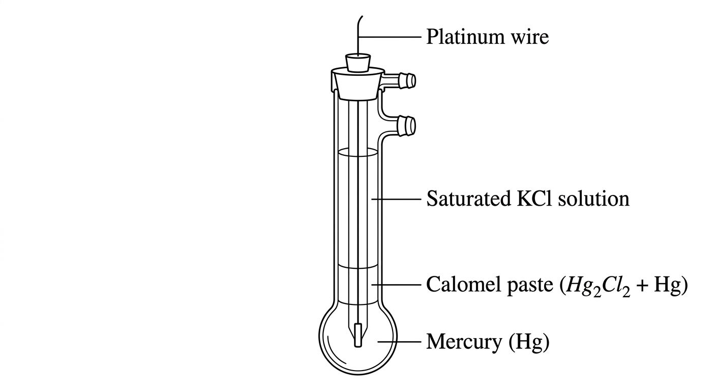
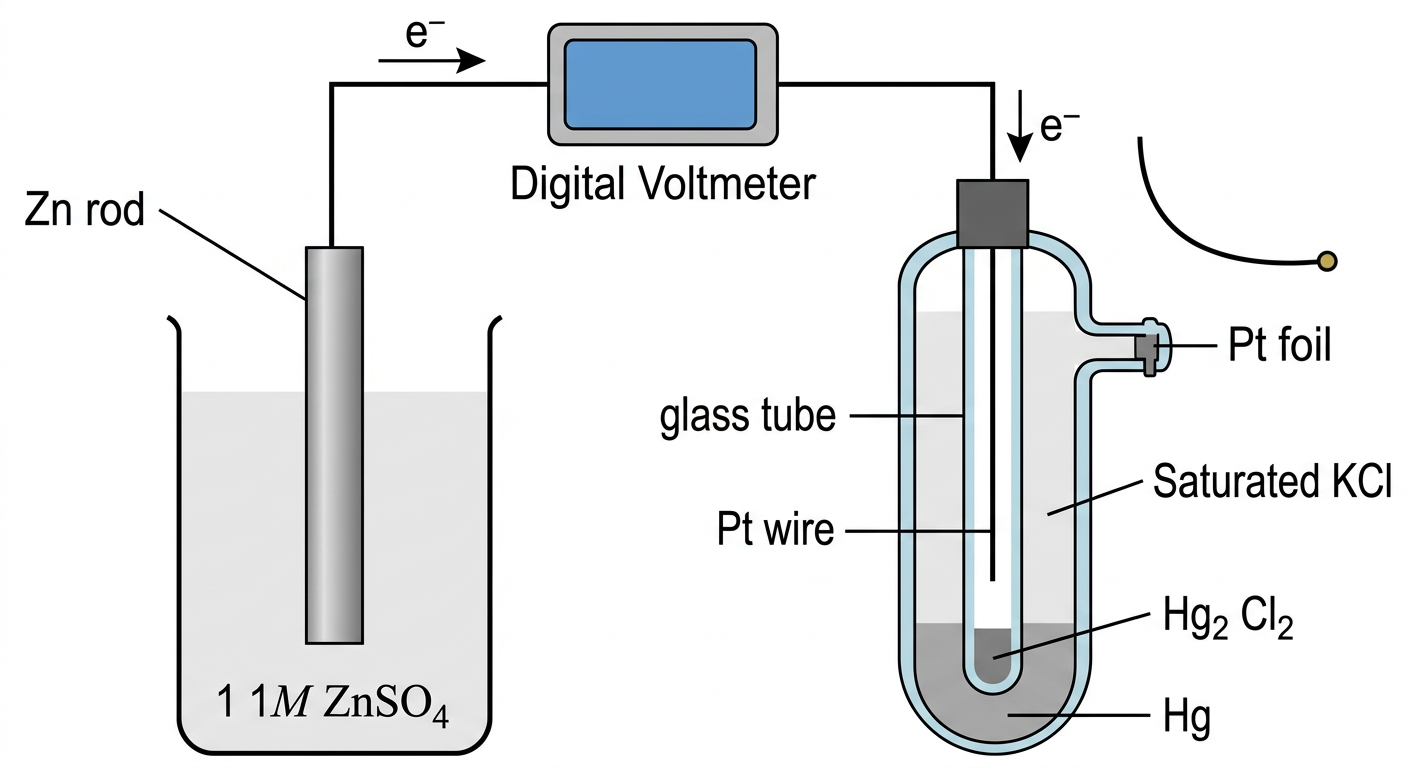
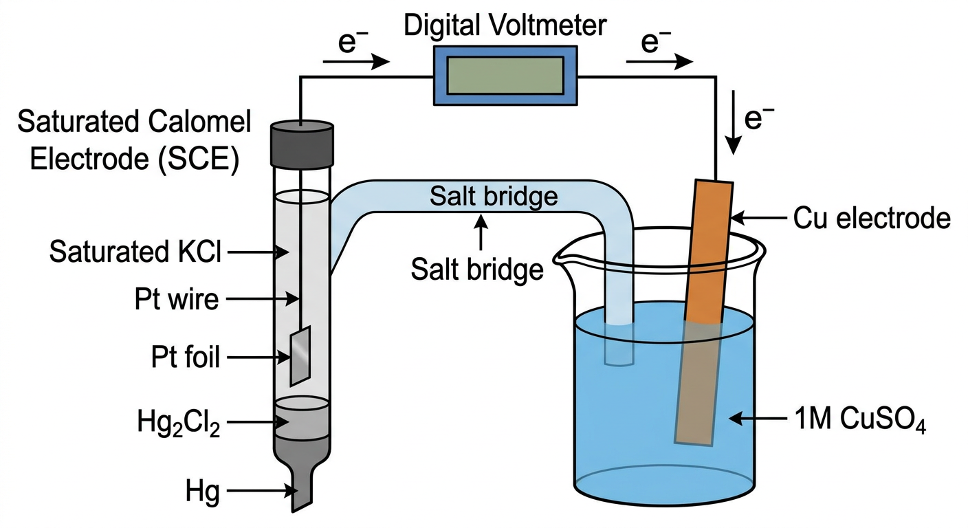
Saturated calomel electrode is a secondary reference electrode. This is an example of metal -metal insoluble metal salt electrode and solution of its common ion.

Construction

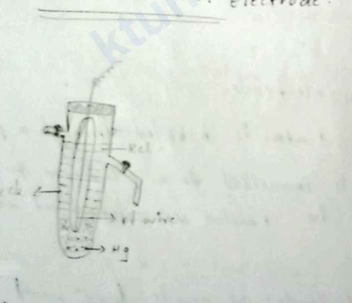
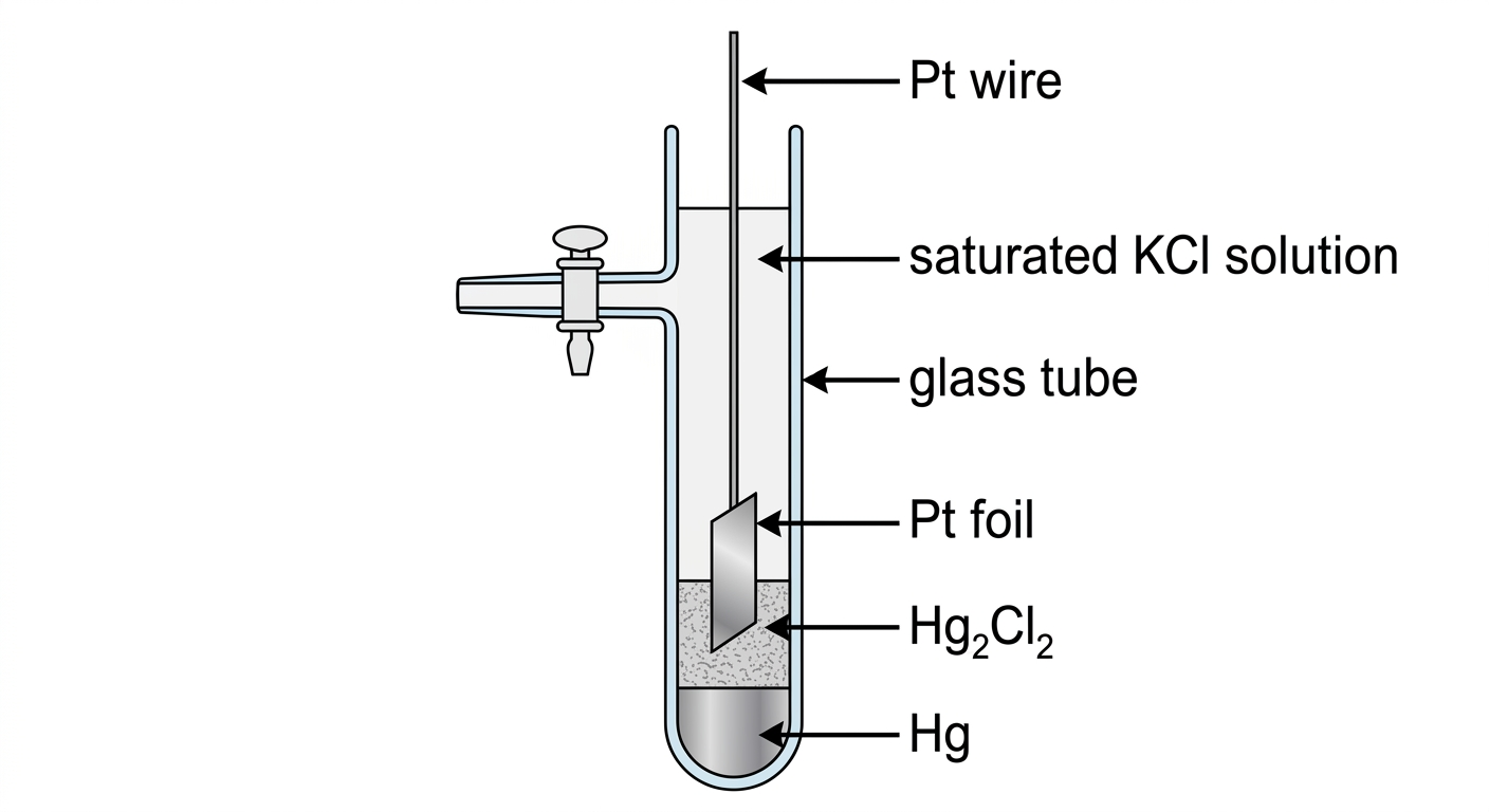
  • It consists of a glass tube in the bottom of which is a layer of Hg.
  • Over the Hg layer, there is a layer of solid mercurous chloride. (Hg2Cl2\text{Hg}_2\text{Cl}_2) • The remaining portion is filled with normal, decinormal or saturated KCl\text{KCl} • A Pt wire is dipped in to the Hg- layer is used for making electrical contact. • The side tube is used for making contact with a salt bridge.
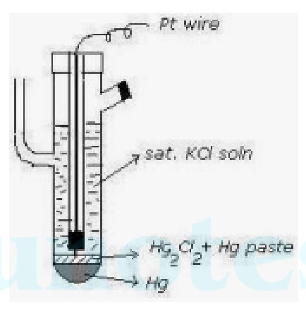
Diagram of a saturated calomel electrode showing glass tube, Pt wire, sat. KCl soln, Hg2Cl2 + Hg paste, and Hg layer.

Working

It can act as an anode or cathode depending on the electrode potential of the coupled electrode.

  • If it can act as anode,

2Hg+2Cl−→Hg2Cl2+2e2\text{Hg} + 2\text{Cl}^- \rightarrow \text{Hg}_2\text{Cl}_2 + 2\text{e} Here the electrode potential of the coupled electrode is greater than calomel electrode. Can be represented as, Hg/Hg2Cl2,KCl\text{Hg} / \text{Hg}_2\text{Cl}_2, \text{KCl} •

If it can act as cathode,

Hg2Cl2+2e−→2Hg+2Cl−\text{Hg}_2\text{Cl}_2 + 2\text{e}^- \rightarrow 2\text{Hg} + 2\text{Cl}^- Here the electrode potential of the coupled electrode is less than that of calomel electrode. Can be represented as KCl,Hg2Cl2/Hg\text{KCl}, \text{Hg}_2\text{Cl}_2 / \text{Hg}

Applying Nernst Equation to reduction reaction,

Ecalomel=Ecalomel0−2.303RTnFlog⁡[Hg]2[Cl−]2[Hg2Cl2]E_{\text{calomel}} = E^0_{\text{calomel}} - \frac{2.303RT}{nF} \log \frac{[\text{Hg}]^2[\text{Cl}^-]^2}{[\text{Hg}_2\text{Cl}_2]}

For solids concentration is taken as 1

Ecalomel=Ecalomel0−2.303RT2Flog⁡[Cl−]2E_{\text{calomel}} = E^0_{\text{calomel}} - \frac{2.303RT}{2F} \log [\text{Cl}^-]^2


Page 13 of 105

Ecalomel=Ecalomel0−2.303RT/Flog⁡[Cl−]E_{calomel} = E_{calomel}^0 - 2.303RT / F \log[Cl^-]

From the above equation it is seen that the potential of the calomel electrode varies with the concentration of the KCl solution used,

Electrode potential of Calomel electrode at different concentrations are

KCl concentration0.1N (DNCE)1N (NCE)Saturated (SCE)
Electrode potential in Volt0.335V0.2810V0.2422V

Applications

  1. Used for determination of electrode potential.
  2. Used to find out pH of an unknown solution.

Limitations

  1. Toxic nature of mercury
  2. cannot be used above 500 c because the mercurous chloride breakdowns yielding an unstable reading.

GLASS ELECTRODE

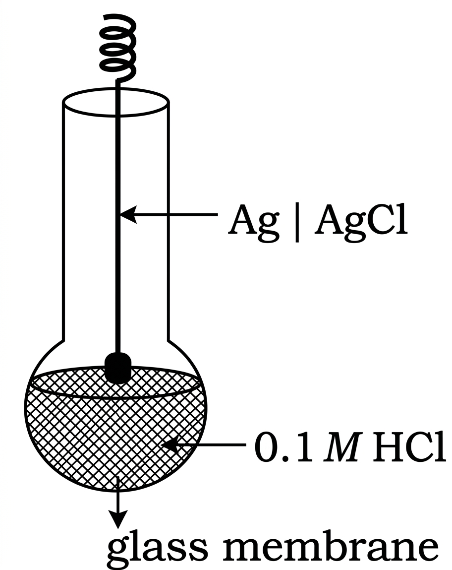
Glass electrode is a secondary reference electrode which produces a constant and reproducible electrode potential. It is ion selective electrodes and used for the pH measurements.

Construction and Working •

It is made up of a special type of glass relatively low melting point and high electrical conductivity

Long glass tube with a thin glass bulb filled with 0.1M HCl0.1\text{M HCl}.

A Pt wire or silver wire coated with a layer of AgCl is inserted into it to make electrical contact.

Composition: Si O2=72%\text{Si O}_2 = 72\%, CaO=6%\text{CaO} = 6\%, Na2O=22%\text{Na}_2\text{O} = 22\%

Electrode representation is, Pt/0.1MHCl,glass/TestH+solution\mathbf{Pt/0.1M HCl, glass/Test H+ solution}

The electrode potential of glass electrode is

EG=EG0+0.0591log⁡[H+]E_G = E_G^0 + 0.0591 \log[H^+]

EG=EG0−0.0591[pH]E_G = E_G^0 - 0.0591[\text{pH}]

EG0E_G^0 is a constant depending upon nature of the glass and pH of the solution taken inside the glass tube . EG0E_G^0 is 0.6V0.6\text{V} or 0.5V0.5\text{V} depending om the variety of the


Page 14 of 105

class

Advantages

  1. It is simple and easily be used.

  2. Used in pH range 0 -12.

  3. The results are accurate.

  4. Can be used in presence of strong oxidising and reducing agents.

  5. It can be used in coloured, turbid and colloidal solutions
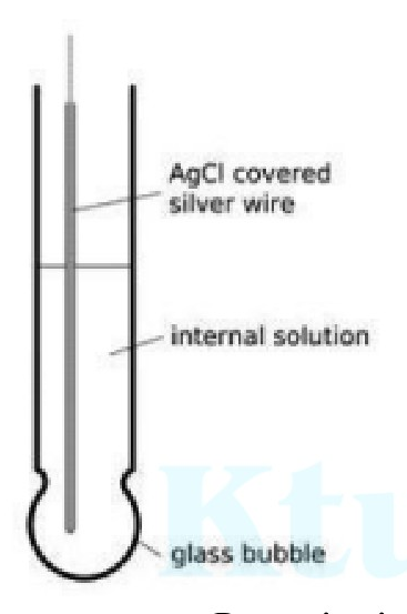
Diagram of a glass electrode showing internal silver wire, AgCl coating, internal solution, and glass bubble.

Determination of pH by using glass electrode

Principle:

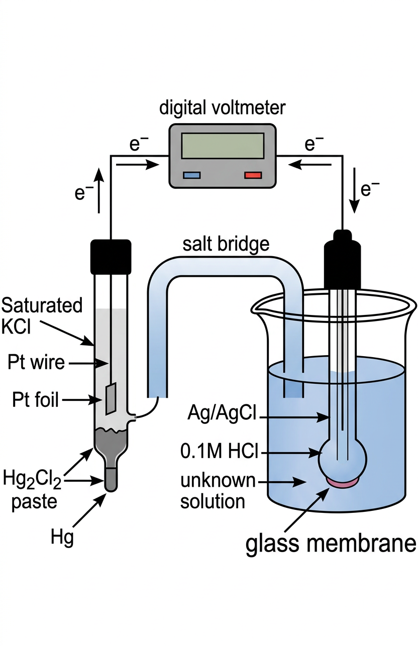
The H+\text{H}^+ ion concentration inside the electrode is constant. When this electrode is dipped in to solution of unknown H+\text{H}^+, it becomes sensitive to the outside concentration in the solution. The potential difference is developed across the membrane. By measuring that potential difference, we can find out pH\text{pH}.

Procedure

In order to measure the potential of glass electrode the unknown solution is taken in beaker, Glass electrode is dipped in it. It is connected to a saturated calomel electrode. emf of the cell is measured. The cell formed is represented as ,

Hg / Hg2Cl2\text{Hg}_2\text{Cl}_2 KCl\text{KCl}// [H+](c=?)\text{[H}^+]_{\text{(c=?)}}/Glass/ H(0.1M)+\text{H}^+_{(0.1\text{M})},Pt,

Ecell=EC−EA\text{Ecell} = \text{E}_\text{C}-\text{E}_\text{A}

Ecell=Eglass−Ecalomel\text{Ecell}= \text{Eglass} - \text{Ecalomel}

Ecell=[EGo−0.0591pH]−0.2422\text{Ecell} = [\text{E}^\text{o}_\text{G} - 0.0591\text{pH}] - 0.2422

Ecell=[EGo−0.0591pH]−0.2422\text{Ecell} =[\text{E}^\text{o}_\text{G} - 0.0591\text{pH}]- 0.2422

Ecell=(EGo−0.2422)−0.0591pH\text{Ecell} =(\text{E}^\text{o}_\text{G} - 0.2422)- 0.0591\text{pH}


Page 15 of 105

This equation has the form Y=C+mXY=C+mX the equation of a straight line having Y intercept C and slope m, when we plot a graph between emf on the Y-axis and pH on the X-axis.

The constants C and m can be determined by calibrating the pHmeter with two buffer solutions of known pH. The intercept C=EG0−0.2422C=E^0_G - 0.2422 and the slope is −0.0591-0.0591 at 25∘C25^\circ\text{C}. The pH of the test solution can be calculated by noting the EcellE_\text{cell} with test solution and knowing the values of C and m.
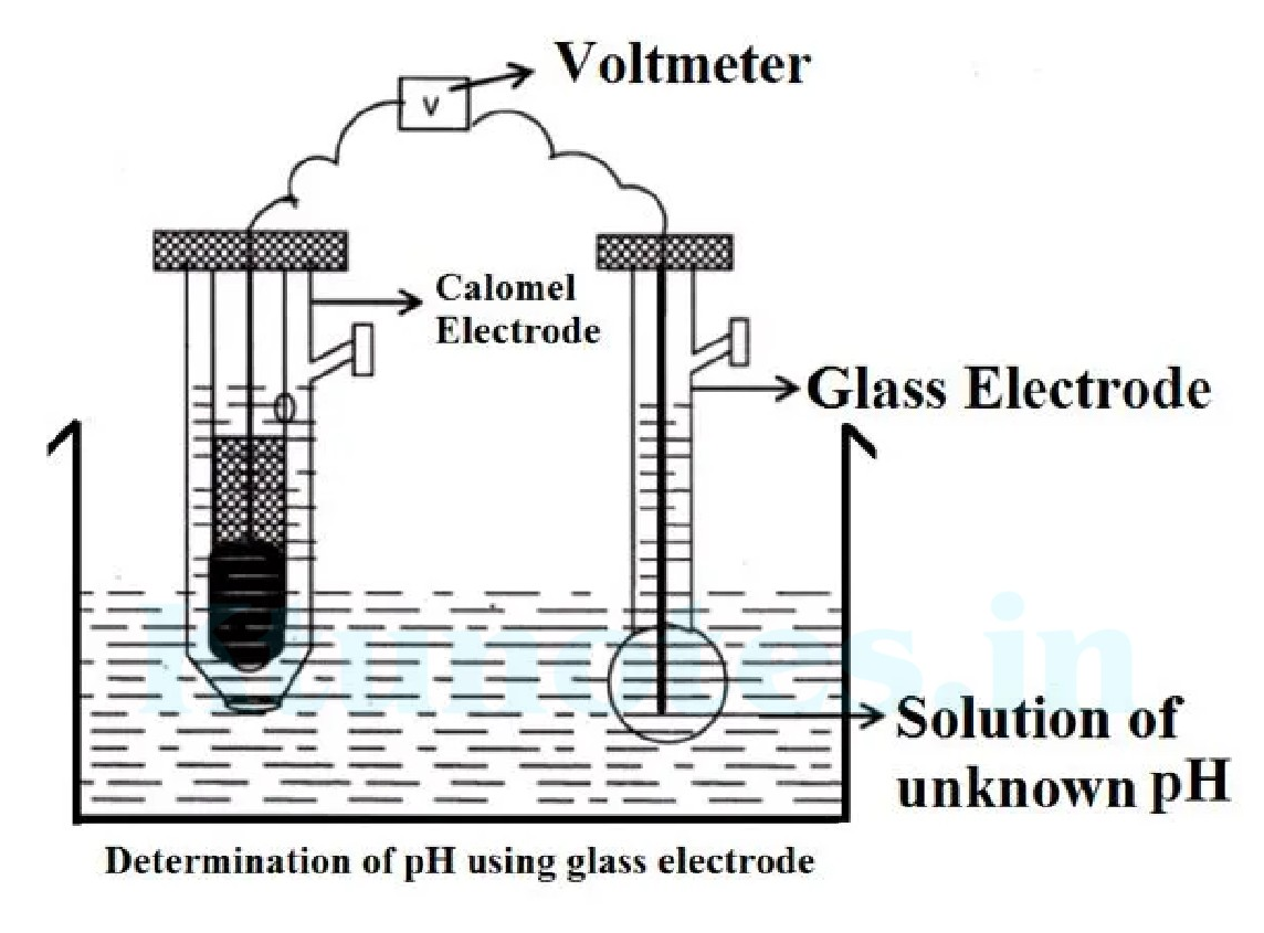
Experimental setup for determination of pH using glass electrode connected to a voltmeter, with a Calomel electrode and a glass electrode immersed in a solution of unknown pH.

Determination of pH using glass electrode

Limitations

  1. As the glass electrode has very high electrical resistance, electronic potentiometer must be used to find EMF.

  2. Due to highly absorptive nature a lot of working is required

  1. A pH buffer solution shows an emf of 208 mV with pH 4 buffer solution and -32 mV with pH 9.2 buffer solution. Find the pH of test solution if it shows an emf of 78 mV.

Ans: The equation has the form y=c+mxy=c+mx. The equation for a straight line having intercept c and slope m when we plot a graph between emf (y-axis) and pH (x-axis).

208=c+4m208 = c + 4m (1)

−32=c+9.2m-32 = c + 9.2m (2)

equation (1)-(2) gives

240=−5.2m240 = -5.2m \quad\quad m=−46.15m = -46.15


Page 16 of 105

substituting in (1)

208=c+4×−46.15c=392.6208 = c + 4 \times -46.15 \quad \quad c = 392.6

Emf of the test solution is

78=c×m×pH78 = c \times m \times \text{pH}

Knowing cc and mm unknown pH\text{pH} can be determined by substituting .

78=392.6+−46.15×pHpH=6.8178 = 392.6 + -46.15 \times \text{pH} \quad \text{pH} = 6.81

TYPES OF CELLS

Commercial cells are used as a source of electrical energy.

There are of three types.

  1. Primary cells- In which cell reactions cannot be reversed. So, it cannot be recharged.

Eg: Daniel cell, Weston cadmium cell

  1. Secondary cells (storage or accumulation cell)- In which cell reaction can be reversed by applying an external source of current.

Eg: Lithium-ion cell, Lead storage battery, Ni-Cd battery.

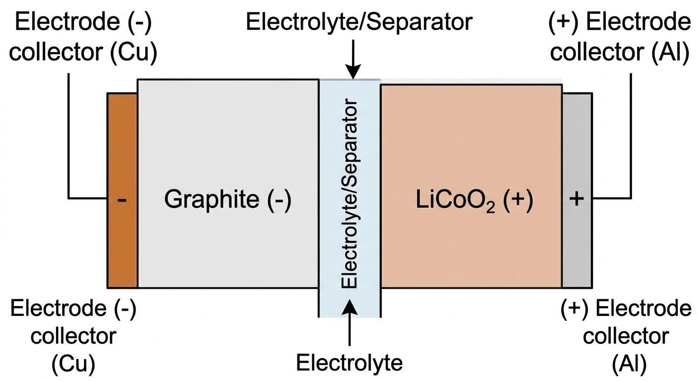
LITHIUM-ION CELL

  • It is a rechargeable battery in which Li ion moves between anode and cathode during charging and discharging.

It is more popular than other batteries because, Li has higher negative value for reduction potential and a lower atomic mass than any other metal.

CONSTRUCTION

In a typical Li ion cell , The positive electrode is made up of crystalline Li metal oxide (LiMO2\text{LiMO}_2) Eg : LiCoO2\text{LiCoO}_2 or LiMnO2\text{LiMnO}_2.

The negative electrode is made up of lithiated graphite or lithiated carbon (LixCG\text{Li}_x\text{C}_\text{G}). Lithium ions are inserted in between the layer of carbon atoms.

Electrolyte is the solution of lithium salt in an organic solvent.(LiBF4\text{LiBF}_4)

A solid electrolyte separator (SEI) separates the anode and cathode.

WORKING

The lithium ion moves from the anode to cathode during discharging and from cathode to anode while charging.

Charging

During Charging the cell act as an electrolytic cell the electrical energy is converted in to chemical energy.

Anode (+)

LiMO2→Li(1−x)MO2+xLi++xe−\text{LiMO}_2 \rightarrow \text{Li}_{(1-x)} \text{MO}_2 + x\text{Li}^+ + x\text{e}^-

Cathode (-)


Page 17 of 105

CG+xLi++xe−→LixCGC_G + x\text{Li}^+ + xe^- \rightarrow \text{Li}_x \text{C}_G

The net cell Reactions is,

LiMO2+CG→LixCG+Li(1−X)MO2\text{LiMO}_2 + \text{C}_G \rightarrow \text{Li}_x \text{C}_G + \text{Li}_{(1-X)} \text{MO}_2

Discharging:

During discharging the cell act as an electrochemical cell where the chemical energy is converted to electrical energy. When the cell acts as an electrochemical cell, LiMO2\text{LiMO2} is the cathode and graphite is the anode.

Anode (-)

LixCG→xLi++xe−+CG (Oxidation)\text{Li}_x \text{C}_G \rightarrow x\text{Li}^{++}xe^-+\text{C}_G \text{ (Oxidation)} These Li+\text{Li}^+ ions produced during oxidation diffuses through the electrolyte and reaches at the cathode for reduction.

Cathode (+)

Li(1-x)MO2+xLi++xe−→LiMO2\text{Li(1-x)}\text{MO}_2 + x\text{Li}^{++}xe^- \rightarrow \text{LiMO}_2

The net cell Reactions is,

LixCG+Li(1−x)MO2→LiMO2+CG\text{LixC}_G+\text{Li}(1-\text{x})\text{MO}_2 \rightarrow \text{LiMO}_2+ \text{C}_G

During discharging the Li cell is represented as,
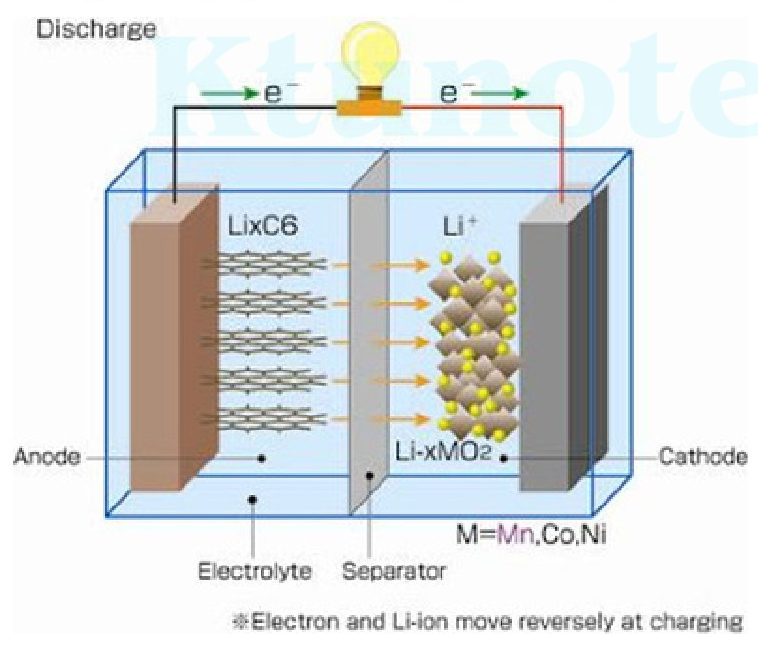
Diagram of a discharging lithium-ion cell

Advantages

  • Li-ion batteries are lighter than other equivalent batteries.
  • Can handle hundreds of charge discharge cycles
  • They do not use poisonous materials like Pb,Hg,Cd\text{Pb}, \text{Hg},\text{Cd} etc

Page 18 of 105

  • Available in different size and shape.
  • They have no memory effect-which means that if do not have completely discharge them before recharging.

Disadvantages

  • They will be destroyed 2 or 3 years from the date of manufacture whether you used them or not.
  • They are extremely sensitive to high temperature.
  • Expensive to manufacture.
  • If they get completely discharged, then destroyed

Applications

  • Used in notebook computers • Mobile phone and other electronic devices. • Used in small digital music devices, MP3 player. • Digital camera. • Laptops. • Military applications.

Li ion cell cannot be charged 100%100\% because when battery is charged to 100100 the reaction becomes, LiMO2→Li(1−1)MO2+xLi++xe−\text{LiMO}_2 \rightarrow \text{Li}_{(1-1)} \text{MO}_2 + \text{xLi}^+ + \text{xe}^- i.e. LiMO2→LiMO2++xLi++xe−\text{LiMO}_2 \rightarrow \text{LiMO}_2^+ + \text{xLi}^+ + \text{xe}^- metal oxides are highly explosive. Hence automatic circuit breakers in Li-ion battery.

Fuel Cells:

A fuel cell is a galvanic cell that converts chemical energy of a fuel and an oxidant directly into electrical energy. A fuel cell can be generally represented as Fuel/-ve electrode/electrolyte/+ve electrode/oxidant\text{Fuel/-ve electrode/electrolyte/+ve electrode/oxidant}.

It is an electrochemical conversion device. It produces electricity by converting the chemical energy of a fuel and an oxidant which reacts in the presence of an electrolyte .

Fuel cells differ from ordinary electrochemical cell because here the reactants are supplied from outside rather than being an integral part of the cell and the energy can be withdrawn indefinitely from a fuel cell as long as the outside supply of fuel is maintained.

It is similar to the electricity generator set, which converts the chemical energy of petrol and air into electricity. It is a power generator rather than a rechargeable battery. The most successful and important fuel cell is hydrogen-oxygen fuel cell.

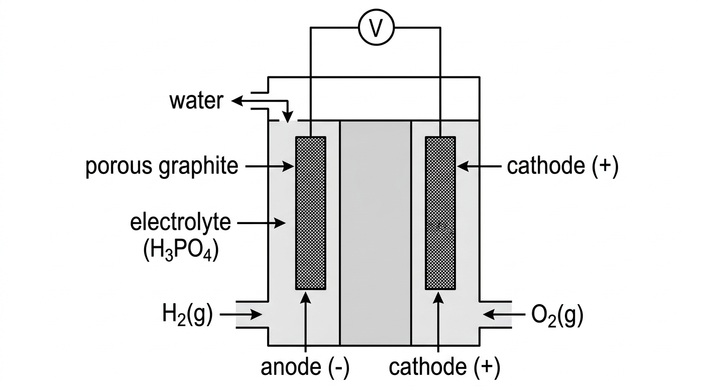
Hydrogen-Oxygen Fuel Cell (acid electrolyte)

The most successful fuel cell is the hydrogen-oxygen fuel cell. It produces electricity based on the reaction: 2H2(g)+O2(g)→2H2O(l)\text{2H}_2\text{(g)} + \text{O}_2\text{(g)} \rightarrow \text{2H}_2\text{O(l)} It uses hydrogen as the fuel and oxygen as the oxidant.

Construction

  • It consists of two porous graphite electrodes with metal catalysts (like platinum).
  • Phosphoric acid is used as the electrolyte. Hydrogen and oxygen gas under pressure (50atm50\text{atm}) are continuously passed through the anodic and cathodic chambers.
  • The cell operates at a temperature of about 150−200∘C150-200^\circ\text{C} because the ionic conductivity of phosphoric acid is very low at low temp.

Page 19 of 105

Heat is generated during the reaction of H2H_2 and O2O_2 so cooling plates are used to maintain the temperature.

The Electrode Reactions are

At anode: 2H2(g)→4H+(aq)+4e−2H_2(\text{g}) \rightarrow 4H^+(\text{aq}) + 4e^- (oxidation of hydrogen)

At cathode: O2(g)+4H+(aq)+4e−→2H2O(l)O_2(\text{g}) + 4H^+(\text{aq}) + 4e^- \rightarrow 2H_2O(\text{l}) (reduction of oxygen)

Overall reaction: 2H2(g)+O2(g)→2H2O(l)2H_2(\text{g}) + O_2(\text{g}) \rightarrow 2H_2O(\text{l})
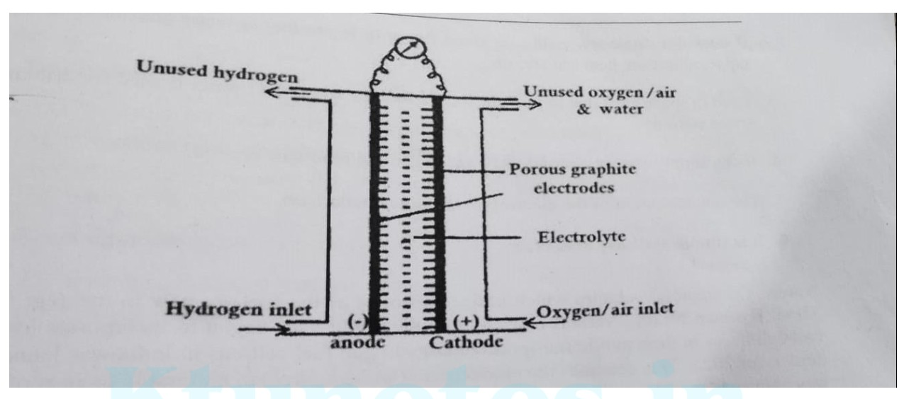
Diagram of a Hydrogen-Oxygen Fuel Cell

Advantages

  1. The fuel cell has high efficiency and can convert about 80%80\% of available chemical energy to electrical energy.
  2. Environmentally Friendly: The only byproduct is water, making them free from pollution, noise, vibration, and heat transfer.
  3. Continuous Energy Supply: They can provide continuous energy as long as reactants are supplied.
  4. Space Applications: Lightweight and the byproduct water is used for drinking in space stations.
  5. Constant Electrolyte Concentration: The concentration of the electrolyte remains unchanged.
  6. Simple and Easy to Operate: They are relatively easy to operate.

Disadvantages of Hydrogen-Oxygen Fuel Cells:

  1. Electro-catalyst Issues: Difficulty in finding a suitable electro-catalyst that functions efficiently for long periods without contamination or deterioration.
  2. Gaseous Fuel Storage and Handling: Gaseous fuels are difficult to store and handle.
  3. Corrosive Electrolyte: The electrolyte used is highly corrosive.
  4. Fuel Purity Requirements: Fuels used must be extremely pure.
  5. High Cost: The technology is expensive.

Page 20 of 105

CONDUCTIVITY

Conductors : A substance or material that allows the passage of electricity, such substances are called conductors.

  • Substance or material that does not allow the passage of electricity, are called non-conductors or insulators.

Types of conductors Conductors are two types

  1. Metallic conductor-Conduct electric current due to movement of electrons E.g.: metals, semiconductors.
  2. Electrolytic conductors-Conduct electric current due to movement of ions . Eg: salt solutions.

Conductance(C) -Reciprocal of resistance . C=1/RC=1/R, Units are ohm-1 (mho) and siemen(s).

Specific resistance or resistivity (ρ\rho) We know that Resistance (R) is directly proportional to length,ll Inversely proportional to area a, i.e R  l/aR \text{ } \boldsymbol{\text{}} \text{ } l/\text{a} R=ρ l/aR=\rho \text{ } l/\text{a}

Specific resistance ( ρ\rho ) is the resistance of a conductor of unit length and unit area of cross section. Unit is  extgreekWcm\text{ extgreek{W}cm}. ρ=R a/ l\rho\text{=} \text{R a/ l}

Specific conductance or conductivity ( extgreekk\boldsymbol{\text{ extgreek{k}}}) It is the reciprocal of specific resistance. It is defined as the conductance of 1cm31\text{cm}^3 of a conductor held between two electrodes of 1cm21\text{cm}^2 area.

K=1/ρ i.e. K=1/R∗l/a\text{K} = 1/\rho \text{ i.e. } \text{K} = 1/\text{R} * l/\text{a}

K=C∗l/a conductance ∗l/a\text{K}= \text{C} * l/\text{a} \text{ conductance } * l/\text{a}

Cell constant It is the ratio of distance between two electrodes (ll) and area of the electrodes (a) Cell constant = ll / a Unit - m−1 or cm−1\text{m}^{-1} \text{ or } \text{cm}^{-1}

Or K=conductance*cellconstant

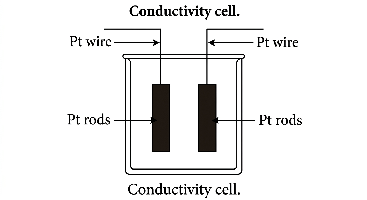
Conductivity cell It consists of two electrode plates coated with Pt black. It is connected to Pt wire, which are sealed through two glass tubes. The tubes are strongly fixed such that distance between electrodes remains unchanged


Page 21 of 105
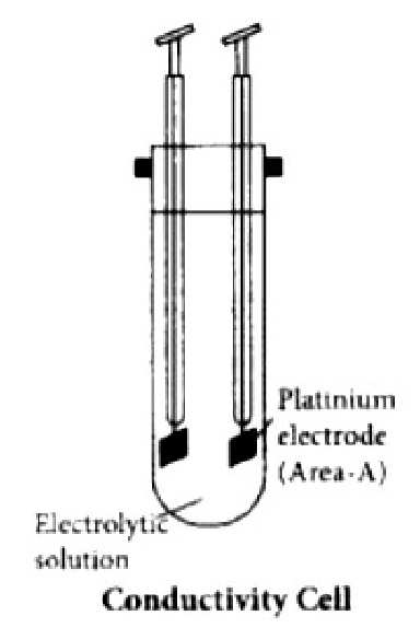
Diagram of a Conductivity Cell showing platinum electrodes and electrolytic solution

Determination of the Cell constant Cell constant may be obtained by measuring 'll' and 'aa'. But it is very difficult to measure the actual area precisely in this type of small cells. Thus in actual practice cell constant is measured by filling the conductivity cell with a solution of known conductivity like 0.1M KCl0.1\text{M KCl} solution . The conductivity of 0.1M KCl0.1\text{M KCl} solution is 0.01288Scm−10.01288\text{Scm}^{-1} at 298K298\text{K}.

Conductivity of 0.1M KCl0.1\text{M KCl} solution (K) = Conductance * Cell constant

By measuring the conductance of 0.1M KCl0.1\text{M KCl} solution in the given cell the cell constant can be determined.

Cell constant=Conductivity of 0.1M KCl solution (K)/Conductance of 0.1M KCl\text{Cell constant} = \text{Conductivity of } 0.1\text{M KCl solution (K)} / \text{Conductance of } 0.1\text{M KCl}

Measurement of Conductivity with a Digital Conductivity Meter:

  • The conductivity cell is connected to the digital conductivity meter and appropriate temperature is selected.
  • The conductivity cell is immersed in the sample solution taken in a beaker.Make sure that the cell is fully immersed in the solution .
  • The meter measures the conductance by selecting the proper range switch. The digital conductivity meter directly reads the conductance.
  • Conductivity is calculated as: Conductivity=Conductance x Cell constant\text{Conductivity} = \text{Conductance x Cell constant}

3. Problem 1.3.1:

  • Calculates the conductivity of a water sample given its conductance (560 μS560\text{ }\mu\text{S}) and the cell constant determined using 0.1 M KCl0.1\text{ M KCl} (conductivity =0.01288 S/cm= 0.01288\text{ S/cm}, conductance =12.34 mS= 12.34\text{ mS}).

Problem 1. Calculate the conductivity of given sample of water at 298K298\text{K},which shows a conductance of 560 micro mho560\text{ micro mho} in the given cell at 298K298\text{K}.A standard solution of 0.1 M KCl0.1\text{ M KCl} shows a conductance of 12.34 mS12.34\text{ mS} in that cell.( Given that conductivity of 0.1 M KCl0.1\text{ M KCl} at 298 K298\text{ K} is 0.001288 ohm−1 cm−10.001288\text{ ohm}^{-1}\text{ cm}^{-1} .

Specific conductance of KCl\text{KCl} solution = conductance×cell constant\text{conductance} \times \text{cell constant}

Cell constant=Sp. conductance of standard KCl solution /conductance of standard KCl in the given\text{Cell constant} = \text{Sp. conductance of standard KCl solution /conductance of standard KCl in the given} 0.01288/12.34×10−3=1.043 cm−10.01288 / 12.34\times 10^{-3} = 1.043\text{ cm}^{-1}


Page 22 of 105

Conductivity of given solution = conductance×cell constant=560×10−6×1.043=583×10−6 cm−1\text{conductance} \times \text{cell constant} = 560 \times 10^{-6} \times 1.043 = 583 \times 10^{-6} \text{ cm}^{-1}

  1. The specific conductivity of 0.3N KCl0.3N \text{ KCl} at 27∘C27^{\circ}\text{C} is 0.028 S cm−10.028 \text{ S cm}^{-1}. The resistance of the cell containing this solution is 300 ohm300 \text{ ohm}. Determine cell constant?

Given that K=0.028 S cm−1K = 0.028 \text{ S cm}^{-1}, R=300 ohmR = 300 \text{ ohm}

specific conductivity(K)=1R×Cell constant\text{specific conductivity} (K) = \frac{1}{R} \times \text{Cell constant}

Cell constant =K×R=0.028×300=8.4 cm−1= K \times R = 0.028 \times 300 = 8.4 \text{ cm}^{-1}

  1. A conductivity cell is found to have two parallel plates of area 1.5 cm21.5 \text{ cm}^2 kept at 9.8 cm9.8 \text{ cm} apart. It gives a resistance of 1500 ohm1500 \text{ ohm} when filled with solution. Find out the cell constant and conductivity of the solution?

Cell constant=la=9.81.5=6.53 cm−1\text{Cell constant} = \frac{l}{a} = \frac{9.8}{1.5} = 6.53 \text{ cm}^{-1}

Specific conductance of KCl\text{KCl} solution = conductance×cell constant\text{conductance} \times \text{cell constant}

=11500×6.53=4.35×10⁻³ ohm−1 cm−1= \frac{1}{1500} \times 6.53 = 4.35 \times 10^{-3} \text{ ohm}^{-1} \text{ cm}^{-1}

CORROSION

Corrosion is a process which involves the slow destruction of a metal as a result of its reaction with moisture and other gases present in the atmosphere.

Corrosion always occurs at anodic areas. More reactive metals are corroded more easily.

All metals and alloys are susceptible to corrosion. Au\text{Au} shows excellent resistance under atmosphere condition, but gets corroded when exposed to Hg\text{Hg} at ambient temperature.

Corrosion is enhanced by the presence of a) impurities b)air and moisture c)electrolytes and strains in metals like dents, scratches etc.

Corrosion of iron is called rusting.

Rust is a hydrated form of ferric oxide, .

Tarnishing of silver, formation of green coating on copper and bronze etc are other examples of corrosion.

TYPES OF CORROSION

Based on environment corrosion is classified into Two types.

  1. Dry or Chemical Corrosion

  2. Wet or Electrochemical Corrosion

Dry or Chemical Corrosion

Direct chemical action of environment/atmosphere gases such as O2\text{O}_2, halogen, H2S\text{H}_2\text{S}, SO2\text{SO}_2, N2\text{N}_2


Page 23 of 105

or Corrosion by other gases.

Wet or Electrochemical Corrosion

The corrosion of metals in aqueous environment is more common than dry corrosions. This type of corrosion takes place when

  • A metal is in contact with a conducting liquid
  • Two dissimilar metals or alloys are immersed or dipped partially in a conducting solution.

According to electrochemical theory

  • Separate anodic and cathodic areas are developed, between which current flows through the conducting medium.
  • At the anodic area (in the metal part) oxidation and generation of electrons takes place.
  • These electrons formed in anodic area moves through the conducting medium, and it is called corrosion current.
  • Environment is the cathodic area where the electrons are received (reduction) non-metallic ions like OH−\text{OH}^- are formed.
  • Diffusion towards the metallic ions formed in the anodic area and non-metallic ions in the cathodic area takes place and the corrosion product is formed in between the anodic and cathodic area.

Mechanism of corrosion (Rusting)

In this type of corrosion one part of the metal becomes anode, flow of electronic current between the anodic and cathodic areas takes place in through an electrolyte in contact with it.

1) Hydrogen evolution corrosion in acidic medium

This Occurs when metals are in contact with acidic solutions in the absence of sufficient oxygen. Eg: Fe or Al in contact with HCl\text{HCl}.

Hydrogen evolution corrosion takes place in the case of Iron immersed in acid medium this is due to the fact that hydrogen electrode potential in acid medium (E0H+/H2=0VE^0 \text{H}^+/\text{H}_2 = 0\text{V}) is higher than electrode potential of iron(E0Fe2+/Fe=−0.44VE^0 \text{Fe}^{2+}/\text{Fe} = -0.44\text{V}).

Reactions:

\text{Anode: } & \text{Fe} \rightarrow \text{Fe}^{2+} + 2\text{e}^- && E^0_{\text{Fe}^{2+}/\text{Fe}} = -0.44\text{V} \ \text{Cathode: } & 2\text{H}^+ + 2\text{e}^- \rightarrow \text{H}_2 && E^0 = 0\text{V} \ \text{Net Reaction: } & \text{Fe} + 2\text{H}^+ \rightarrow \text{Fe}^{2+} + \text{H}_2 && E^0_{\text{cell}} = 0 - (-0.44) = 0.44\text{V} align*} **This type of corrosion occurs when a metal displaces hydrogen ions ($\text{H}^+$) from an acidic solution.** **Metals with higher negative reduction potentials, like iron (Fe), zinc (Zn), and aluminum (Al), act as the anode and corrode.** **Metals with positive reduction potentials, like copper (Cu) and silver (Ag), act as the cathode and** ---

Page 24 of 105

receive some galvanic protection.

  1. Hydrogen Evolution in Alkaline Medium:

Iron doesn't undergo hydrogen evolution corrosion in an alkaline medium because the hydrogen electrode potential in alkaline conditions (-0.828 V) is lower than iron's electrode potential (-0.44 V).

However, metals like aluminum can experience hydrogen evolution in alkaline environments because hydrogen electrode potential in alkaline conditions (-0.828 V) is higher than the electrode potential of Aluminium (-1.66 V)

Anode , Al→Al3++3eE0=−1.66V\text{Al} \rightarrow \text{Al}^{3+}+ 3\text{e} \quad \text{E}^0 = -1.66\text{V}

Cathode . 2H2O+2e→H2+2OH− E0=−0.828V2\text{H}_2\text{O} +2\text{e} \rightarrow \text{H}_2+ 2\text{OH}^-\text{ E}^0 = -0.828\text{V}

Corrosion cell potential is Ecell=Ecathode−Eanode=0.832V\text{Ecell} = \text{Ecathode}- \text{Eanode} = 0.832\text{V}

  1. Oxygen Absorption Corrosion in Acidic Medium:

This happens when metals come into contact with water containing dissolved oxygen in acidic or neutral conditions Eg : Rusting of iron.

Reactions:

Anode Fe→Fe2++2eE0Fe2+/Fe=−0.44V\qquad \text{Fe} \rightarrow \text{Fe}^{2+} + 2\text{e} \quad \text{E}^0\text{Fe}^{2+}/\text{Fe} = -0.44\text{V}

Cathode O2+4H++4e→2H2OE0=1.23V\qquad \text{O}_2 + 4\text{H}^+ + 4\text{e} \rightarrow 2\text{H}_2\text{O} \quad \text{E}^0 = 1.23\text{V}

E0cell=Ecathode−Eanode=1.67V\text{E}^0\text{cell} = \text{Ecathode}- \text{Eanode} = 1.67\text{V}

Fe2+\text{Fe}^{2+} produced can be further oxidized to Fe3+\text{Fe}^{3+} in acidic or neutral environments. Fe3+\text{Fe}^{3+} produced forms an insoluble precipitate of Fe(OH)3\text{Fe(OH)}3 which is called yellow rust.

In presence of limited supply of oxygen the corrosion product is the black rust Fe3O4\text{Fe}_3\text{O}_4(black rust).

The rust formation leads to intense localized corrosion called pitting corrosion
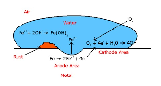
Diagram showing pitting corrosion of iron with an anode area, cathode area, rust, water drop, and oxygen

  1. Oxygen Absorption Corrosion in alkaline Medium:

This happens when metals come into contact with water containing dissolved oxygen in alkaline environment. Eg : Rusting of iron.


Page 25 of 105

Anode Fe→Fe2++2eE0Fe2+/Fe=−0.44V\quad\quad\quad\quad\quad\text{Fe} \rightarrow \text{Fe}^{2+} + 2\text{e} \quad \text{E}^0\text{Fe}^{2+}/\text{Fe} = -0.44\text{V}

Cathode: O2+2H2O+4e→4OH− E0=+0.40V\text{O}_2 + 2\text{H}_2\text{O} + 4\text{e} \rightarrow 4\text{OH}^-\ \text{E}^0 = +0.40\text{V}

Here corrosion cell potential in acid medium is:

Ecell=Ecathode−Eanode=0.40−(−0.44)=0.84V\text{Ecell} = \text{Ecathode} - \text{Eanode} = 0.40 - (-0.44) = 0.84\text{V}

The variation of potential with pH of oxygen electrode is given by E=1.23−0.0591pH\text{E} = 1.23 - 0.0591\text{pH}

For alkaline solution pH can be taken as 14 and therefore E=1.23−(0.0591×14)=+0.40V\text{E} = 1.23 - (0.0591 \times 14) = +0.40\text{V}

Fe2+\text{Fe}^{2+} produced here cannot further oxidized to Fe3+\text{Fe}^{3+} in alkaline environments, since oxygen electrode potential is less than (E0Fe3+/Fe2+=+0.77V)(\text{E}^0 \text{Fe}^{3+}/\text{Fe}^{2+} = +0.77\text{V}) in alkaline medium.

Here no insoluble precipitate of Fe(OH)3\text{Fe(OH)}_3 is produced, thus no intense localized corrosion

Galvanic series

Galvanic series which gives real and useful information regarding corrosion behaviour of metals and alloys in a given environment. It is a series obtained by arranging metals and alloys in the order of corrosion tendencies.

Mg, Mg alloys, Zn, Al, Cd, Mild Steel, Cast iron, Solder, Pb, Sn, Brass, Cu, Ni, Stainless steel, Cr, Ag, Ti, Au, Pt \qquad\qquad\qquad\qquad\qquad\qquad decreasing order of corrosion (Galvanic Series)

ELECTROCHEMICAL SERIESGALVANIC SERIES
A series in which the metals and arranged in the increasing order of their Standard Reduction PotentialA series in which the metal electrodes are nonmetals are arranged in the increasing order of their corrosion tendency.
The position of a given metal in electrochemical series is fixedPosition may shift.
E0\text{E}^0 is measured for metals and non-metals.No information regarding position of alloys
It tells the relative displacement tendencies.Predicts relative corrosion tendencies
Electrode potential is measured by using SHE as reference electrode.Electrode potential is measured by using SCE as reference electrode
E0\text{E}^0 is measured by dipping pure metals in their 1M salt solutionE0\text{E}^0 is measured by dipping metals and non-metals in unpolluted sea water

CATHODIC PROTECTION


Page 26 of 105

Cathodic protection is a method of preventing a metallic object from corrosion. It is an electrochemical process in which the metal which is to be protected is forced to act as cathode.

A metal surface buried or immersed can contain anodic and cathodic areas. Corrosion occurs only in the anodic area. Therefore the entire surface of the metal can be turned into a cathode, then the corrosion can be prevented.

Two main methods of applying cathodic protection are

i. Sacrificial anode protection

ii. Impressed current cathodic protection

(1) Sacrificial anode protection

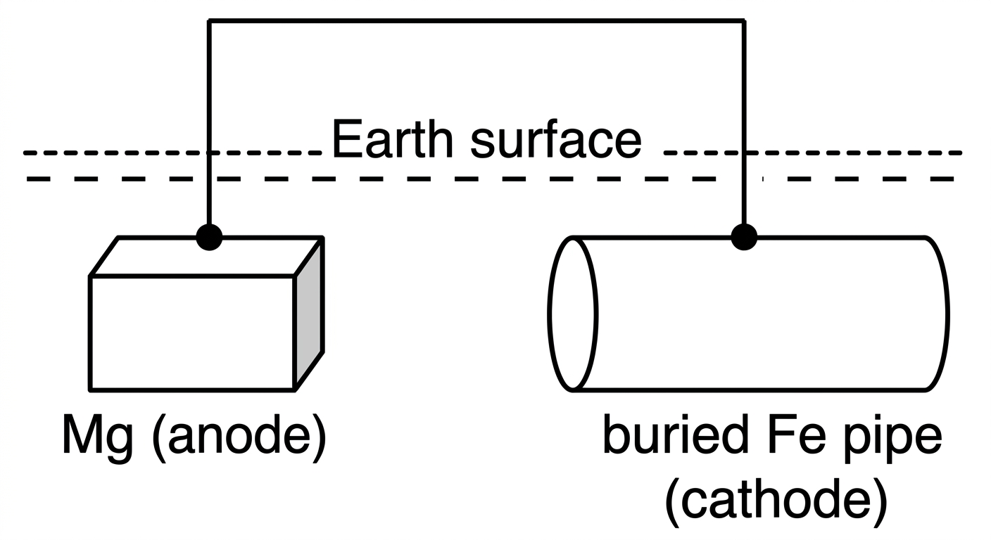
In this method, the metallic structure which is to be protected is connected to a more anodic metal through a wire, so the entire corrosion is concentrated on the anodic metal, and the metallic structure is protected sacrificially. Example for anodic metals; Mg, Zn, Al and its alloys.
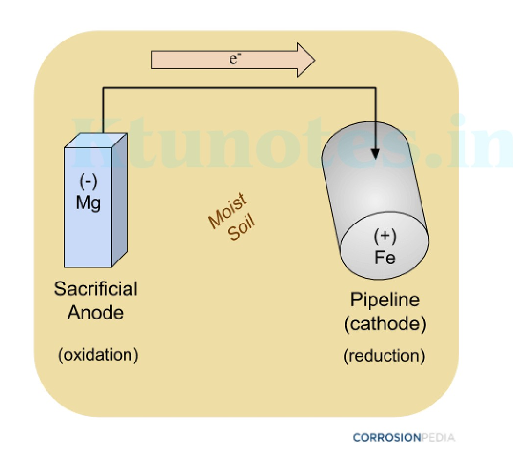
Diagram of sacrificial anode protection showing a magnesium anode connected to an iron pipeline through a wire in moist soil

Sacrificial anode systems are based on the position of the metal in the galvanic series. Metals at the top of the series are more prone to corrosion. Sacrificial anode systems are more reliable than the impressed current system because lesser quantity of the component is destroyed and no power supply is required.

Advantages


Page 27 of 105

  1. No external power is required 2. Easy to install and inexpensive 3. Minimum maintenance required

Applications

Protection of buried pipelines, underground cables, marine structures, ship body, open water tank coolers, condensers etc.

(2) Impressed current cathodic protection

This widely used system is usually developed to protect a structure which is immersed in a high resistivity electrolyte such as fresh water or sandy soils.

This method requires large amount of current. As a result of corrosion an electric flow occurs from the anodic region to the cathodic part, which is known as corrosion current.

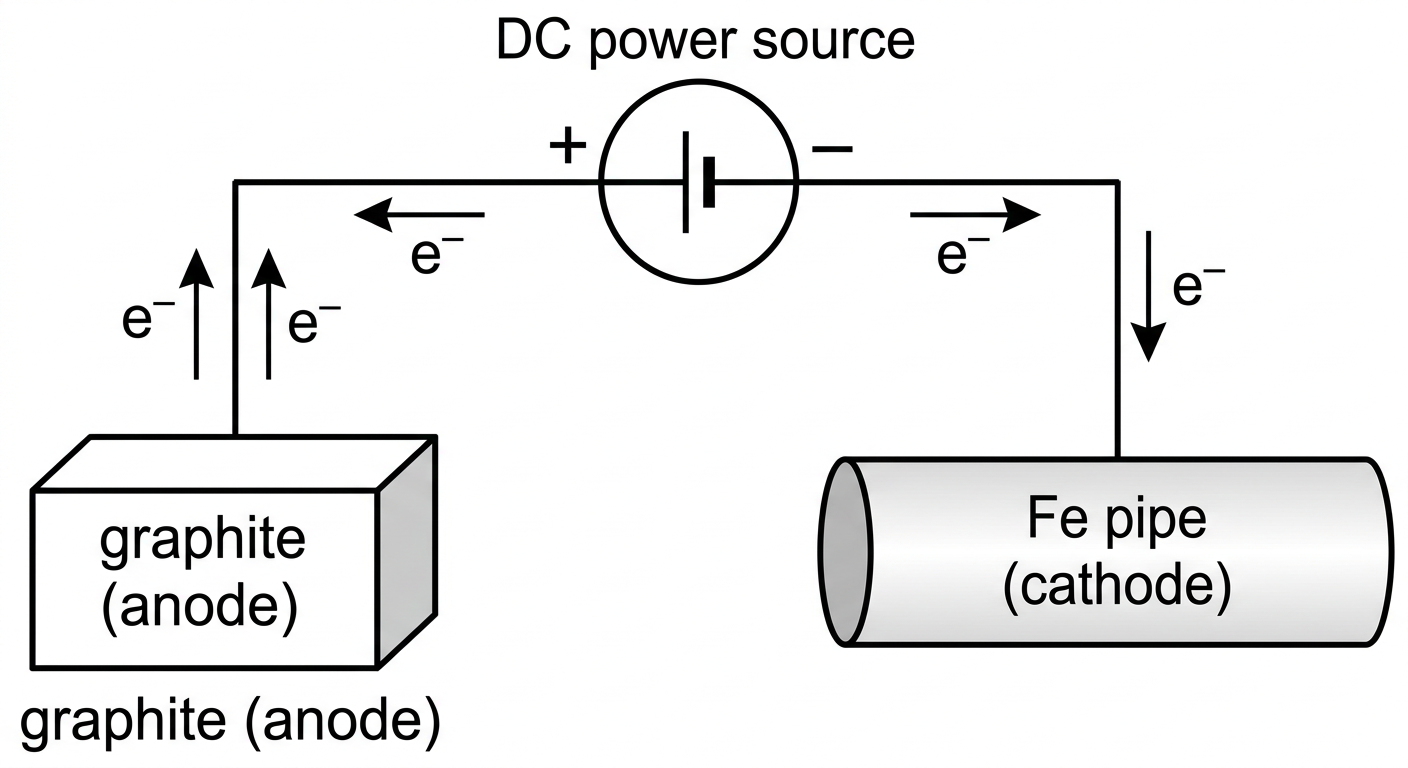
An impressed current is applied in opposite direction to neutralize corrosion current and convert the corroding metal from anode to cathode. Usually impressed current is derived from a battery or DC source with an insoluble anode like graphite or silica
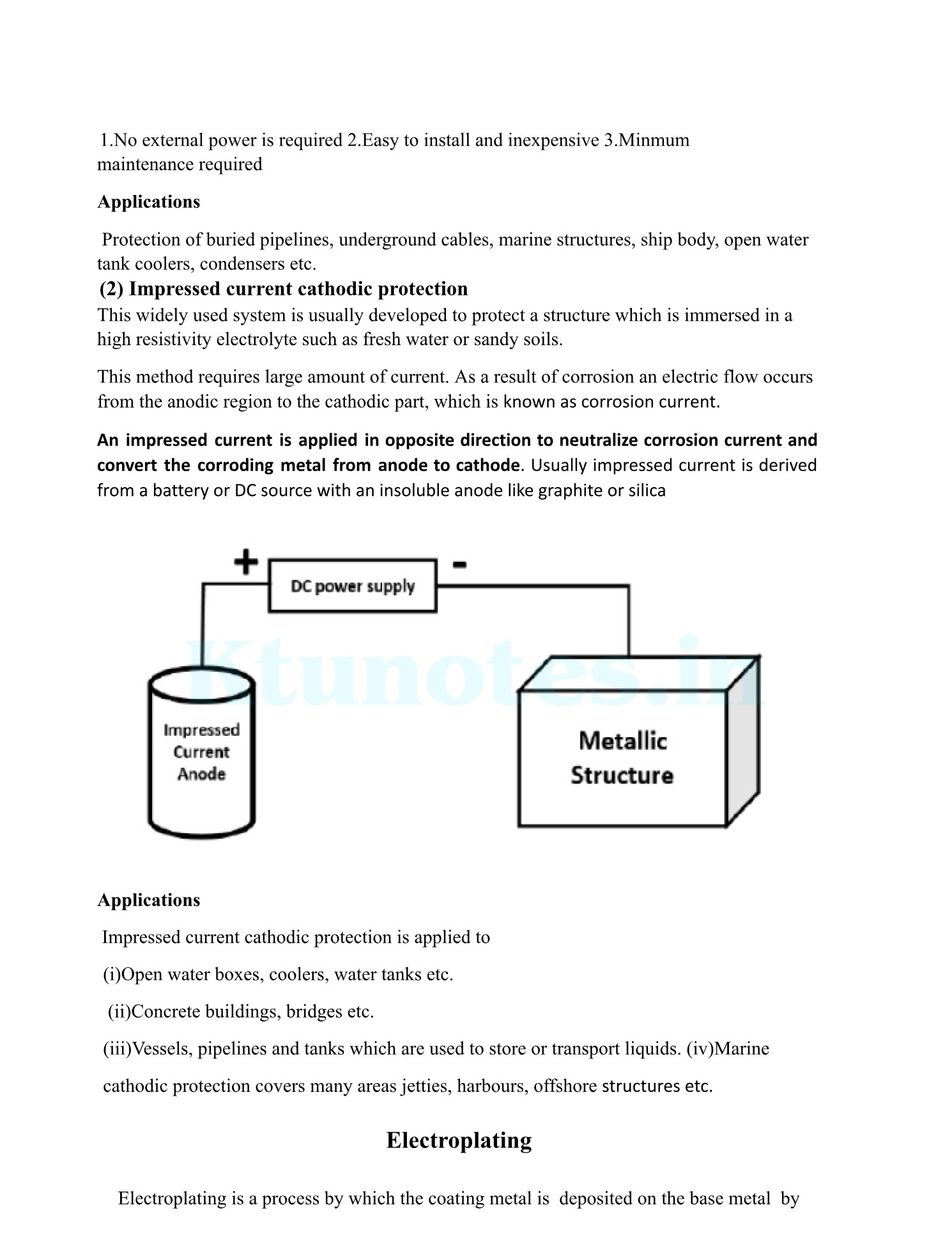
Schematic diagram of impressed current cathodic protection system

Applications

Impressed current cathodic protection is applied to

(i) Open water boxes, coolers, water tanks etc.

(ii) Concrete buildings, bridges etc.

(iii) Vessels, pipelines and tanks which are used to store or transport liquids. (iv) Marine cathodic protection covers many areas jetties, harbours, offshore structures etc.

Electroplating

Electroplating is a process by which the coating metal is deposited on the base metal by


Page 28 of 105

passing a direct current through an electrolytic solution containing the soluble salt of the coating metal

Theory of electroplating

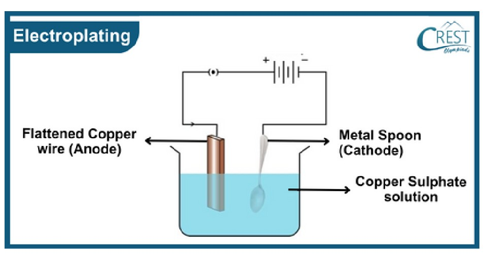
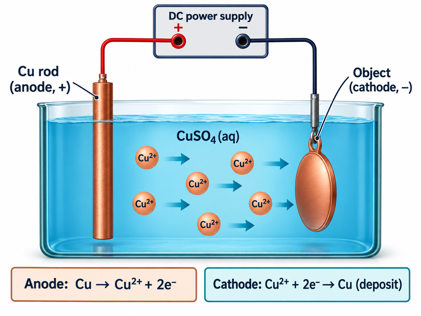
The object to be plated is the cathode of the electrolytic cell and the anode is either the plating metal or an inert material of good electrical conductivity like graphite. The electrolyte is a soluble salt solution of the coating metal.

When DC current is passed through the electrolyte electrolysis occurs and the metal is coated on the surface of the solution.

Objectives of Electroplating:

  • To improve corrosion resistance
  • To increase chemical attack and wear resistance
  • To enhance physical appearance and hardness
  • To improve surface properties
  • To increase decorative and commercial value

Copper Electroplating:

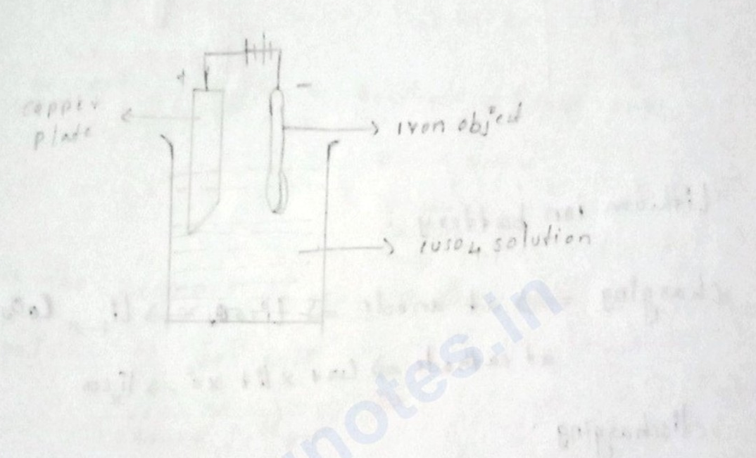
The article to be plated is cleaned to remove oil, grease, and surface impurities. It is then treated with dilute acid (like HCl\text{HCl} or H2SO4\text{H}_2\text{SO}_4) to remove oxides and scales. The cleaned article is then made as cathode of the electrolytic cell. Pure copper metal rod is taken as anode. Both the electrodes are dipped in copper sulphate solution. DC current is passed through the electrolyte electrolysis occurs and Cu2+\text{Cu}^{2+} move towards the cathode and gets deposited there.

Anode Cu→Cu2++2e\quad \text{Cu} \rightarrow \text{Cu}^{2+} + 2\text{e}

Cathode Cu2++2e→Cu\quad \text{Cu}^{2+} + 2\text{e} \rightarrow \text{Cu}

Electroplating setup diagram


Page 29 of 105

f the anode is made of some inert material like graphite, then electrolytic salt is added continuously in order to maintain proper coating metal ion concentration in the electrolytic bath.

Moreover, the process of electroplating goes on non-stop, since the anode is not consumed and its replacement is not required. When inert electrode is used, anode reaction can be represented as

H2O→2H++1/2 O2+2e\text{H}_2\text{O} \rightarrow 2\text{H}^+ + 1/2\text{ O}_2 + 2\text{e}

For brighter and smooth deposits, favorable conditions such as low temperature, medium current density and low metal ion concentration are used.

Applications of copper electroplating

  1. Steel articles used in automobile industry are generally given three successive coatings of Cu, Ni and Cr. This is done for corrosion protection and to impart shining and clear metal appearance.
  2. Copper electroplating is used in decorative items, kitchen wares, jewelry etc. to enhance the aesthetic appearance.

Electroless plating

Electroless plating is a chemical, autocatalytic, metal coating process without the use of electricity.

Principle

In this process metal piece, which is to be plated is immersed in a mixture of a reducing agent and a complex compound. It produces a deposition of continuous coating layer, on the surface, by a controlled chemical reduction that is catalysed by the metal or alloy being deposited

Metal ions + Reducing agent →\rightarrow Metal plated over a catalytically active surface + oxidised product.

Electroless plating is used to deposit a conductive surface on a non- conductive object to improve its electroplating

Process of Electroless plating

Process of Electroless plating involves the following steps

  1. Preparation of the surface to be plated: In this step the surface is activated by,

The surface of the metal which is to be washed thoroughly,

a) Etching: Removal of impurities by acid treatment

b) Electroplating: A thin layer of the metal to be plated or any other suitable metal is coated on the surface of the object

c) Chemical treatment: The plastic objects and printed circuit boards are treated with SnCl2\text{SnCl}_2 and PdCl2\text{PdCl}_2


Page 30 of 105

  1. Preparation of Plating bath : The plating bath should include the following

a) A soluble salt of the metal (chlorides and sulphates) b) Complexing Agents like EDTA, tartrate citrate etc to prevent excess deposition c) Reducing agents like Sodium thio Sulphate, Formaldehyde etc d) Accelerators like succinates, glycinates, fluorides etc to increase the plating rate. e) Stabilizers like Calcium ions, lead ions, thio urea etc to prevent decomposition of the bath and to impart stability to the solution f) Buffer solution like Rochelle salt, Boric acid to maintain pH

  1. Procedure: The article to be plated is immersed in the bath containing the metal salt and reducing agent. The plating is carried out in a series of tanks .The rate of deposition is controlled by the amount of reducing agent and the type of complexing agent

Advantages

  1. No electricity required.
  2. Can be used to obtain uniform coating on irregular shaped articles.
  3. The deposits are more compact and highly adherent.
  4. No elaborate arrangements are required.
  5. Coating provides better wear resistance
  6. The coating is less porous and provides better corrosion resistance.
  7. Improved hardness, strength, ductility

Electroless -Copper plating.

Electroless copper plating is used to deposit a layer of copper on substrate without the use of electricity.

The object which is to be plated is degreased using organic solvents followed by acid treatment .This object is then immersed in plating bath containing cupric salt ,reducing agents,buffer and complexing agent.

Soluble salt is the Copper sulphate, formaldehyde is the reducing agent a. buffer (NaOH )complexing agent EDTA is taken in the plating bath. Metal surface(metal)which is to be plated is introduced into the bath and then heated. The electroless plating of copper take place as follows.

At cathode

Cu2++2e−⟶Cu\text{Cu}^{2+} + 2\text{e}^- \longrightarrow \text{Cu}

At anode

2HCHO+4OH−⟶2HCOO−+2H2O+H2↑2\text{HCHO} + 4\text{OH}^- \longrightarrow 2\text{HCOO}^- + 2\text{H}_2\text{O} + \text{H}_2 \uparrow


Page 31 of 105

Over all reaction is

Cu2++2HCHO+4OH−⟶Cu+2HCOO−+2H2O+H2\text{Cu}^{2+} + 2\text{HCHO} + 4\text{OH}^- \longrightarrow \text{Cu} + 2\text{HCOO}^- + 2\text{H}_2\text{O} + \text{H}_2

Applications of electroless copper plating

  1. This type of coating is mainly used in double or multilayered printed circuit boards in which plating through holes is required.
  2. This is used as base coating for subsequent electroplating.
  3. Numerous consumer goods are coated by this method to create durable and attractive surfaces.

Limitations

  1. The complexing agent creates difficulties.

  2. Formaldehyde is a human health hazard.

  3. Calculate the emf for the cell, Zn/Zn2+//Ag+/Ag\text{Zn} / \text{Zn}^{2+} // \text{Ag}^+ / \text{Ag} given EZn2+/Zn0=−0.762 vE^0_{\text{Zn}^{2+}/\text{Zn}} = -0.762\text{ v} and EAg+/Ag0=0.8 vE^0_{\text{Ag}^+/\text{Ag}} = 0.8\text{ v}

    A: Given cell is Zn/Zn2+//Ag+/Ag\text{Zn} / \text{Zn}^{2+} // \text{Ag}^+ / \text{Ag}. EZn2+/Zn0=−0.762 vE^0_{\text{Zn}^{2+}/\text{Zn}} = -0.762\text{ v}, EAg+/Ag0=0.8 vE^0_{\text{Ag}^+/\text{Ag}} = 0.8\text{ v}, Ecell0=Eright0−Eleft0=0.8−(−0.762)=1.562 vE^0_{\text{cell}} = E^0_{\text{right}} - E^0_{\text{left}} = 0.8 - (-0.762) = 1.562\text{ v}

    Applying Nernst eqn

    Ecell=Ecell0−0.0591nlog⁡[p]/[R]E_{\text{cell}} = E^0_{\text{cell}} - \frac{0.0591}{n} \log [\text{p}] / [\text{R}] n=2n=2

  4. Calculate the ECu2+/Cu0E^0_{\text{Cu}^{2+}/\text{Cu}}, given ECu2+/Cu0=0.296 vE^0_{\text{Cu}^{2+}/\text{Cu}} = 0.296\text{ v} and [Cu2+]=0.015M[\text{Cu}^{2+}] = 0.015\text{M} E=E0+0.05912log⁡0.296E = E^0 + \frac{0.0591}{2} \log 0.296

  5. Write the half cell and net cell reactions for the following cell, Zn/ZnSO4 (aq)//CuSO4 (aq)/Cu\text{Zn} / \text{ZnSO}_4\text{ (aq)} // \text{CuSO}_4\text{ (aq)} / \text{Cu}. Calculate the standard emf of the cell given, EZn2+/Zn0=−0.76 vE^0_{\text{Zn}^{2+}/\text{Zn}} = -0.76\text{ v} and ECu2+/Cu0=+0.34 vE^0_{\text{Cu}^{2+}/\text{Cu}} = +0.34\text{ v}.

    A: Half cell reactions At anode: Zn⟶Zn2++2e−\text{Zn} \longrightarrow \text{Zn}^{2+} + 2\text{e}^- At cathode: Cu2++2e−⟶Cu\text{Cu}^{2+} + 2\text{e}^- \longrightarrow \text{Cu} Net cell reaction =Zn+Cu2+⟶Zn2++Cu= \text{Zn} + \text{Cu}^{2+} \longrightarrow \text{Zn}^{2+} + \text{Cu}. Ecell0=ECathode0−EAnode0=ECu2+/Cu0−EZn2+/Zn0=0.34−(−0.76)=1.1 vE^0_{\text{cell}} = E^0_{\text{Cathode}} - E^0_{\text{Anode}} = E^0_{\text{Cu}^{2+}/\text{Cu}} - E^0_{\text{Zn}^{2+}/\text{Zn}} = 0.34 - (-0.76) = 1.1\text{ v}.

UNIVERSITY QUESTIONS

Calculate the equilibrium constant for the following reaction at 25∘C25^\circ\text{C} Fe(s)+Cu2+(aq)=Fe2+(aq)+Cu (s)\text{Fe(s)} + \text{Cu}^{2+}\text{(aq)} = \text{Fe}^{2+}\text{(aq)} + \text{Cu (s)} Given EFe2+/Fe0=−0.44 VE^0_{\text{Fe}^{2+}/\text{Fe}} = -0.44\text{ V}, ECu2+/Cu0=0.34 VE^0_{\text{Cu}^{2+}/\text{Cu}} = 0.34\text{ V}.

Log K=nEcell0/0.0591\text{Log } K = n E^0_{\text{cell}} / 0.0591 Ecell0=0.34−(−0.44)=0.78VE^0_{\text{cell}} = 0.34 - (-0.44) = 0.78\text{V}

2×0.78/0.0591=26.392 \times 0.78 / 0.0591 = 26.39 K=log⁡−126.39K = \log^{-1} 26.39

  1. Give the electrochemical reaction taking place when an iron nail is dipped in dil. HCl\text{dil. HCl}. EFe2+/Fe0=−0.44 VE^0_{\text{Fe}^{2+}/\text{Fe}} = -0.44\text{ V}, EFe3+/Fe0=−0.04 VE^0_{\text{Fe}^{3+}/\text{Fe}} = -0.04\text{ V}, EH+/H20=0 VE^0_{\text{H}^+/\text{H}_2} = 0\text{ V}.

Page 32 of 105

When an iron nail is dipped in HCl\text{HCl} two cells are developed. (Fe2+\text{Fe}^{2+} and Fe3+\text{Fe}^{3+})

Emf of the first cell (Fe2+/Fe//H+/H\text{Fe}^{2+}/\text{Fe}//\text{H}^+/\text{H}) =Ecathode−Eanode=0−(−0.44)=0.44V= E_{\text{cathode}} - E_{\text{anode}} = 0 - (-0.44) = 0.44\text{V}

Emf of the second cell (Fe3+/Fe/H+/H\text{Fe}^{3+}/\text{Fe}/\text{H}^+/\text{H}) =0−(−0.04)=0.04V= 0 - (-0.04) = 0.04\text{V}

The emf of the first cell is higher so the reaction takes place in Fe2+\text{Fe}^{2+}

So Fe2++2 HClFeCl2+H2\text{Fe}^{2+} + 2\text{ HCl} \quad\rule{3cm}{0.15mm}\quad \text{FeCl}_2 + \text{H}_2

  1. Why Mg corrodes in both acidic and alkaline oxygen deficient conditions, whereas Fe does not corrode in alkaline oxygen deficient condition? Mg2++2e−→Mg\text{Mg}^{2+} + 2e^- \rightarrow \text{Mg}, E0=−2.36 VE^0 = -2.36\text{ V}, Fe2++2e−→Fe\text{Fe}^{2+} + 2e^- \rightarrow \text{Fe}, E0=−0.44 VE^0 = -0.44\text{ V}, H++e−→1/2H2\text{H}^+ + e^- \rightarrow 1/2\text{H}_2, E0=0E^0 = 0

The electrode potential of H2\text{H}_2 electrode (EE) =−0.0591pH= -0.0591\text{pH} (O2O_2 deficient)

When pH=0\text{pH} = 0, E=0E = 0 (acidic condition)

When pH=14\text{pH} = 14, E=−0.0591×14=−0.8274VE = -0.0591 \times 14 = -0.8274\text{V}

In the case of Mg\text{Mg}, both in acid and alkaline condition E0E^0 of Mg\text{Mg} (−2.36-2.36) is less than the electrode potential of H2\text{H}_2. So Mg\text{Mg} corrode in both acidic and alkaline conditions. But in the case of Fe\text{Fe}, in alkaline condition the E0E^0 of Fe\text{Fe} (−0.44V-0.44\text{V}) is greater than E0E^0 of H2\text{H}_2 (−0.82V-0.82\text{V}) so Fe\text{Fe} do not corrode in alkaline condition.


Page 33 of 105

[Non-content page]


Page 34 of 105

MODULE - 1

ELECTRO CHEMISTRY & CORROSION

⇒\Rightarrow It is the conversion of electrical energy to chemical energy and vice versa.

Electrochemical cellElectrolytic cell⇒Discharge of lithium ion⇒Charging of lithium ionbatterybattery⇒conversion of chemical energy⇒conversion of electricalinto electrical energyenergy into chemical energy⇒using a spontaneous⇒using electricity, nonchemical reaction, electricityspontaneous chemical reactioncan be generated.can be conducted.eg: Daniel celleg: Electrolysis of metallurgiccell→Anode is negatively chargedwhile cathode is positively⇒Anode is positively chargedcharged.and cathode is negatively⇒Generally salt bridge ischarged.used.\begin{array}{|c|c|} \hline \text{Electrochemical cell} & \text{Electrolytic cell} \\ \hline \Rightarrow \text{Discharge of lithium ion} & \Rightarrow \text{Charging of lithium ion} \\ \text{battery} & \text{battery} \\ \hline \Rightarrow \text{conversion of chemical energy} & \Rightarrow \text{conversion of electrical} \\ \text{into electrical energy} & \text{energy into chemical energy} \\ \hline \Rightarrow \text{using a spontaneous} & \Rightarrow \text{using electricity, non} \\ \text{chemical reaction, electricity} & \text{spontaneous chemical reaction} \\ \text{can be generated.} & \text{can be conducted.} \\ \hline \text{eg: Daniel cell} & \text{eg: Electrolysis of metallurgic} \\ & \text{cell} \\ \hline \rightarrow \text{Anode is negatively charged} & \\ \text{while cathode is positively} & \Rightarrow \text{Anode is positively charged} \\ \text{charged.} & \text{and cathode is negatively} \\ \hline \Rightarrow \text{Generally salt bridge is} & \text{charged.} \\ \text{used.} & \\ \hline \end{array}

Page 35 of 105

→\rightarrow Generally anode & cathode are in different container. →\rightarrow Generally anode & cathode are in same or different container.

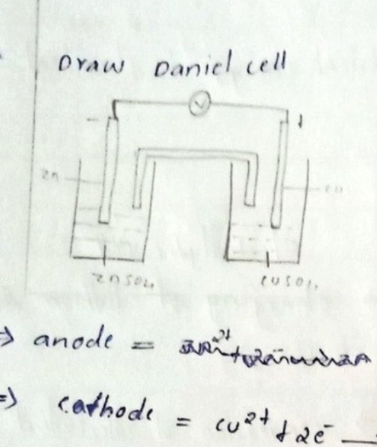
  • Draw Daniel cell

Diagram of a Daniel cell showing two half-cells connected by a salt bridge and a voltmeter

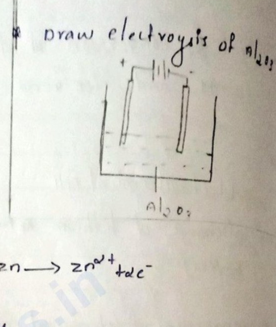
  • Draw electrolysis of Al2O3Al_2O_3

Diagram of an electrolysis cell for Al_2O_3

→\rightarrow anode=\text{anode} = [illegible] Zn→Zn2++2e−\text{Zn} \rightarrow \text{Zn}^{2+} + 2\text{e}^{-}

→\rightarrow cathode=Cu2++2e−→Cu\text{cathode} = \text{Cu}^{2+} + 2\text{e}^{-} \rightarrow \text{Cu}

  • What is salt bridge, write it's two uses.

A) Salt bridge is U-tube shaped bridge.

Uses

→\rightarrow used to maintain electrical neutrality.

→\rightarrow complete the circuit.


Page 36 of 105

ELECTRODE POTENTIAL

→\rightarrow When a metal rod dipped in it's salt solution there are two possibilities

i) either oxidation will occur, by lose of electron

M(s)⟶Mn+(aq)+neˉ\underset{(s)}{M} \longrightarrow \underset{(aq)}{M^{n+}} + n\bar{e}

ii) or reduction will occur, By gain of electron

Mn+(aq)+neˉ⟶M(s)\underset{(aq)}{M^{n+}} + n\bar{e} \longrightarrow \underset{(s)}{M}


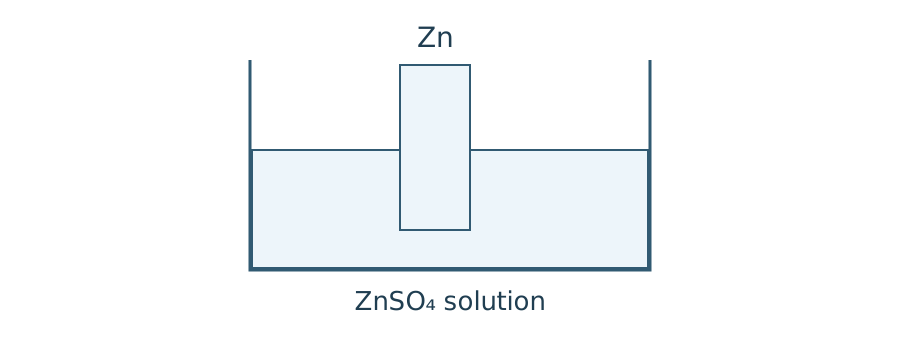
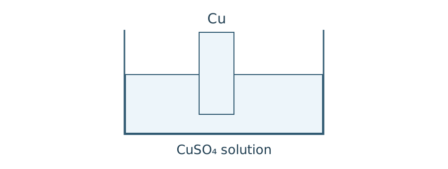
When Zn rod dipped in ZnSO4ZnSO_4 solutionWhen Cu rod dipped in CuSO4CuSO_4 solution

Zinc rod dipped in ZnSO4 solution in a beaker

|

Copper rod dipped in CuSO4 solution in a beaker

| | Zn(s)⟶Zn(aq)2++2eˉ\text{Zn}_{(s)} \longrightarrow \text{Zn}_{(aq)}^{2+} + 2\bar{e} | Cu(aq)2++2eˉ⟶Cu(s)\text{Cu}_{(aq)}^{2+} + 2\bar{e} \longrightarrow \text{Cu}_{(s)} | | Metal surface is -vely charged and is atracted by positively charged ions. | →\rightarrow Metal surface is +vely charged and is atracted by negatively charged ions. |

→\rightarrow These charged layers are called Helmholts electrical double layer.


Page 37 of 105

=> The potential difference associated with these charged layers are called electrode potential.

  • The electrode potential is the tendency of metal to gainor lose\overset{\text{or lose}}{\text{gain}} of electrons when it is in contact with it's own salt solution.

Standard electrode potential [E0][E^0] unit = volt.

  • It is the tendency of an element to lose or gain electron when it is in contact with it's 1 molar salt solution at 25∘c25^{\circ}\text{c} [standard solution].

Electrochemical series & it's applications

  • Different elements are listed on their standard reduction potential value.

  • It is measured based on SHE as reference electrode [ESHE∘=0vE^{\circ}_{\text{SHE}} = 0\text{v}]


Page 38 of 105

[Non-content page]


Page 39 of 105

=> electrode with high negative electrode potential, it can be easily oxidised and very good reducing agent.

Code
e.g. : Lithium electrode $\left[\text{Li}^+/\text{Li}\right]$

⇒\Rightarrow Hydrogen displacement reaction.

⇒\Rightarrow When Zn\text{Zn} rod dipped in H2SO4\text{H}_2\text{SO}_4 solution hydrogen displacement reaction occurs.

Code
$E^0_{\text{Zn}^{2+}/\text{Zn}} = -0.76\text{ V} < E^0_{\text{H}^+/\text{H}_2} = 0\text{ V}$ .

⇒\Rightarrow H2SO4+Zn⟶ZnSO4+H2\text{H}_2\text{SO}_4 + \text{Zn} \longrightarrow \text{ZnSO}_4 + \text{H}_2 .

⇒\Rightarrow When Cu\text{Cu} rod dipped in H2SO4\text{H}_2\text{SO}_4 solution hydrogen displacement reaction does not occurs.

Code
$E^0_{\text{Cu}^{2+}/\text{Cu}} > E^0_{\text{H}^+/\text{H}_2}$ .

⇒\Rightarrow metal displacement reaction.

Code
When $\text{Zn}^{\text{rod}}$ dipped in $\text{CuSO}_4$ solution $\text{Zn}$ oxidise and $\text{Cu}$ reduce. so metal displacement reaction occurs .

$E^0_{\text{Zn}^{2+}/\text{Zn}} = -0.76\text{ V}$

Page 40 of 105

ASSIGNMENT

  • What is electrochemical series.

The electrochemical series, also called the activity series, is a list of metals arranged in order of their standard electrode potentials.

  • Write it's applications.

Predicting redox reaction; corrosion preventation, metal reactivity, electroplating and electrorefining.

  • Explain four applications of the electrochemical series with suitable examples.
  1. Prediting spontaneity of redox reaction.

Zinc reduces copper ions to copper.

Zn+Cu2+⟶Zn2++Cu\text{Zn} + \text{Cu}^{2+} \longrightarrow \text{Zn}^{2+} + \text{Cu}

  1. Corrosion preventation.

To prevent corrosion, iron coated with a layer of zinc, which is more reactive and will sacrifices itself to protect iron. eg: iron.


Page 41 of 105

  1. Designing electrochemical cell.

Zinc is used as the anode and copper is used as the cathode. This combination generates a significant voltage due to their positions in the electrochemical series.

e.g: zinc-copper battery.

  1. Electroplating

silver can be electroplated into copper, because silver is lower in the electrochemical series than copper. Copper will not displace silver, ensuring a stable coating.

e.g: silver.

Nernst equation of a electrode.

⇒\Rightarrow It is for to determine the electrode potential at any concentration.

∞\infty consider an electrode reaction.

M(aq)n++ne−⟶M(s)M^{n+}_{(aq)} + ne^- \longrightarrow M_{(s)}


Page 42 of 105

The free energy change associated with this electrode reaction is:

ΔG=ΔG∘+RTln⁡Q— (1)\Delta G = \Delta G^\circ + RT \ln Q \quad \text{--- } (1)

ΔG=\Delta G = Gibbs free energy

ΔG∘=\Delta G^\circ = standard Gibbs free energy

R=R = gas constant (8.3148.314)

T=T = Temperature in Kelvin

Q=Q = Reaction quotient

Q=[pdt][reactnt]=1[Mn+][e−]n=1[Mn+]Q = \frac{[pdt]}{[reactnt]} = \frac{1}{[M^{n+}][e^-]^n} = \frac{1}{[M^{n+}]}

⇒ΔG=−nFEcell— (a)\Rightarrow \Delta G = -nFE_{\text{cell}} \quad \text{--- } (a)

⇒ΔG∘=−nFEcell∘— (b)\Rightarrow \Delta G^\circ = -nFE^\circ_{\text{cell}} \quad \text{--- } (b)

n=n = no. of electrons in mole

F=F = Faraday's constant [96500 C][96500 \text{ C}]

eq. (1) ⇒\Rightarrow

−nFEelec=−nFEelec∘+RTln⁡1[Mn+]— (1)-nFE_{\text{elec}} = -nFE^\circ_{\text{elec}} + RT \ln \frac{1}{[M^{n+}]} \quad \text{--- } (1)

eq. (1) ÷\div by −nF-nF

Eelec=Eelec∘−RTnFln⁡1[Mn+]E_{\text{elec}} = E^\circ_{\text{elec}} - \frac{RT}{nF} \ln \frac{1}{[M^{n+}]}


Page 43 of 105

∴Eele=Eele∘+RTnFln⁡[Mn+]\therefore E_{\text{ele}} = E^\circ_{\text{ele}} + \frac{RT}{nF} \ln [M^{n+}]

EMn+/M=EMn+/M∘+RTnFln⁡[Mn+]E_{M^{n+}/M} = E^\circ_{M^{n+}/M} + \frac{RT}{nF} \ln [M^{n+}]

EMn+/M=EMn+/M∘+2.303RTnFlog⁡[Mn+]E_{M^{n+}/M} = E^\circ_{M^{n+}/M} + \frac{2.303 RT}{nF} \log [M^{n+}]

at 25∘C=298 K25^\circ\text{C} = 298\text{ K}.

EMn+/M=EMn+/M∘+0.0591nlog⁡[Mn+]\boxed{E_{M^{n+}/M} = E^\circ_{M^{n+}/M} + \frac{0.0591}{n} \log [M^{n+}]}

Write the Nernst equation for zinc electrode ?

Znn++2e−⟶Zn\text{Zn}^{n+} + 2e^- \longrightarrow \text{Zn}

EZn2+/Zn=EZn2+/Zn∘+2.303RTnFlog⁡[Zn2+].E_{\text{Zn}^{2+}/\text{Zn}} = E^\circ_{\text{Zn}^{2+}/\text{Zn}} + \frac{2.303 RT}{nF} \log [\text{Zn}^{2+}].

Write Nernst equation for zinc electrode at 25∘C25^\circ\text{C}.

EZn2+/Zn=EZn2+/Zn∘+0.05912log⁡[Zn2+]E_{\text{Zn}^{2+}/\text{Zn}} = E^\circ_{\text{Zn}^{2+}/\text{Zn}} + \frac{0.0591}{2} \log [\text{Zn}^{2+}]


Page 44 of 105

Calculate the electrode potential of zinc electrode the following conc. of ZnSO4\text{ZnSO}_4 solution.

(i) 0.10.1 molar ZnSO4\text{ZnSO}_4 (ii) 11 molar ZnSO4\text{ZnSO}_4 (iii) 1010 molar ZnSO4\text{ZnSO}_4

(i) EZn2+/Zn=EZn2+/Zn∘+0.05912log⁡[Zn2+]E_{\text{Zn}^{2+}/\text{Zn}} = E^{\circ}_{\text{Zn}^{2+}/\text{Zn}} + \frac{0.0591}{2} \log[\text{Zn}^{2+}] =−0.76+0.05912log⁡0.1= -0.76 + \frac{0.0591}{2} \log 0.1 =−0.76+0.05912×−1= -0.76 + \frac{0.0591}{2} \times -1 =−0.79 V= -0.79\text{ V}

(ii) EZn2+/Zn=EZn2+/Zn∘+0.05912[log⁡1]E_{\text{Zn}^{2+}/\text{Zn}} = E^{\circ}_{\text{Zn}^{2+}/\text{Zn}} + \frac{0.0591}{2} [\log 1] =−0.76+(0.05912)×0= -0.76 + \left(\frac{0.0591}{2}\right) \times 0 =−0.76 V= -0.76\text{ V}

(iii) =EZn2+/Zn=EZn2+/Zn∘+0.05912[log⁡10]= E_{\text{Zn}^{2+}/\text{Zn}} = E^{\circ}_{\text{Zn}^{2+}/\text{Zn}} + \frac{0.0591}{2} [\log 10] =−0.76+(0.05912)×1= -0.76 + \left(\frac{0.0591}{2}\right) \times 1 =−0.73 V= -0.73\text{ V}


Page 45 of 105

=> electrochemical series can provide electrode potential at standard condition. [1 molar conc., 25∘C25^{\circ}\text{C}, 1 atm1\text{ atm}]

=> by using Nernst equation can calculate electrode potential at any concentration.

  • write the Nernst equation for Cu\text{Cu} electrode at 25∘C25^{\circ}\text{C}.

A) Cu2++2e−⟶Cu\text{Cu}^{2+} + 2e^- \longrightarrow \text{Cu}

ECu2+/Cu=ECu2+/Cu∘+0.05912log⁡(Cu2+)E_{\text{Cu}^{2+}/\text{Cu}} = E^\circ_{\text{Cu}^{2+}/\text{Cu}} + \frac{0.0591}{2} \log (\text{Cu}^{2+})

  • IMP consider the electrode reaction Fe3++1e−⟶Fe2+\text{Fe}^{3+} + 1e^- \longrightarrow \text{Fe}^{2+} write the Nernst equation at 25∘C25^{\circ}\text{C}.

A) EFe3+/Fe2+=EFe3+/Fe2+∘+0.05911log⁡[Fe3+Fe2+]E_{\text{Fe}^{3+}/\text{Fe}^{2+}} = E^\circ_{\text{Fe}^{3+}/\text{Fe}^{2+}} + \frac{0.0591}{1} \log \left[\frac{\text{Fe}^{3+}}{\text{Fe}^{2+}}\right]

  • write the electrode reaction Sn4++2e−⟶Sn2+\text{Sn}^{4+} + 2e^- \longrightarrow \text{Sn}^{2+}

A) ESn4+/Sn2+=ESn4+/Sn2+∘+0.05912log⁡[Sn4+Sn2+]E_{\text{Sn}^{4+}/\text{Sn}^{2+}} = E^\circ_{\text{Sn}^{4+}/\text{Sn}^{2+}} + \frac{0.0591}{2} \log \left[\frac{\text{Sn}^{4+}}{\text{Sn}^{2+}}\right]


Page 46 of 105

Nernst equation: worked examples

1. Iron redox electrode

At 25∘C25^{\circ}\mathrm{C}, [Fe2+]=0.01 M[\mathrm{Fe}^{2+}]=0.01\,\mathrm{M}, [Fe3+]=0.1 M[\mathrm{Fe}^{3+}]=0.1\,\mathrm{M} and E∘=0.77 VE^{\circ}=0.77\,\mathrm{V}.

Fe3++e−→Fe2+\mathrm{Fe}^{3+}+e^-\rightarrow\mathrm{Fe}^{2+}

E=E∘+0.0591log⁡10[Fe3+][Fe2+]E=E^{\circ}+0.0591\log_{10}\frac{[\mathrm{Fe}^{3+}]}{[\mathrm{Fe}^{2+}]}

E=0.77+0.0591log⁡100.10.01=0.8291 V≈0.83 V.E=0.77+0.0591\log_{10}\frac{0.1}{0.01}=0.8291\,\mathrm{V}\approx0.83\,\mathrm{V}.

Arithmetic correction: the handwritten notes give 0.82 V. Substituting their stated concentrations gives 0.8291 V.

2. Aluminium electrode

Given [Al3+]=2 M[\mathrm{Al}^{3+}]=2\,\mathrm{M} and E∘=−1.66 VE^{\circ}=-1.66\,\mathrm{V}:

Al3++3e−→Al\mathrm{Al}^{3+}+3e^-\rightarrow\mathrm{Al}

E=−1.66+0.05913log⁡102≈−1.6541 V≈−1.65 V.E=-1.66+\frac{0.0591}{3}\log_{10}2\approx-1.6541\,\mathrm{V}\approx-1.65\,\mathrm{V}.


Page 47 of 105

Nernst equation for cell

eg : Daniel cell.

→\rightarrow zinc electrode as anode. →\rightarrow copper electrode as cathode.

E_{\text{cell}} &= E_{\text{cathode}} - E_{\text{anode}} \ &= E_{\text{Cu}^{2+}/\text{Cu}} - E_{\text{Zn}^{2+}/\text{Zn}} \ &= \bkt{E^{\circ}_{\text{Cu}^{2+}/\text{Cu}} + \frac{2.303 RT}{nF} \text{log} [\text{Cu}^{2+}]} - \bkt{E^{\circ}_{\text{Zn}^{2+}/\text{Zn}} + \frac{2.303 RT}{nF} \text{log} [\text{Zn}^{2+}]} &= E^{\circ}_{\text{Cu}^{2+}/\text{Cu}} - E^{\circ}_{\text{Zn}^{2+}/\text{Zn}} + \frac{2.303 RT}{nF} \bkt{\text{log} [\text{Cu}^{2+}] - \text{log} [\text{Zn}^{2+}]} \ E_{\text{cell}} &= E^{\circ}_{\text{cell}} + \frac{2.303 RT}{nF} \text{log} \frac{[\text{Cu}^{2+}]}{[\text{Zn}^{2+]}} \cdot \text{ at } 25^{\circ}\text{C} : E_{\text{cell}} &= E^{\circ}_{\text{cell}} + \frac{0.0591}{n} \text{log} \frac{[\text{Cu}^{2+}]}{[\text{Zn}^{2+}]} ---

Page 48 of 105

Imp Nernst equation for Cu-Ag cell

ECu2+/Cu0=+0.34 VE^0_{Cu^{2+}/Cu} = +0.34\text{ V} --- anode

EAg+/Ag0=+0.80 VE^0_{Ag^+/Ag} = +0.80\text{ V} --- cathode

⇒\Rightarrow reaction at anode Cu(s)⟶Cu2+(aq)+2e−\text{Cu}_{(s)} \longrightarrow \underset{(aq)}{\text{Cu}^{2+}} + 2e^{-}<br>

⇒\Rightarrow reaction at cathode Ag+(aq)+1e−⟶Ag(s)\underset{(aq)}{\text{Ag}^+} + 1e^{-} \longrightarrow \text{Ag}_{(s)}

2Ag++2e−⟶2Ag2\text{Ag}^+ + 2e^{-} \longrightarrow 2\text{Ag}

Ecell=Ecell0+0.05912log⁡[Ag+]2[Cu2+]E_{\text{cell}} = E_{\text{cell}}^0 + \frac{0.0591}{2} \log \frac{[\text{Ag}^+]^2}{[\text{Cu}^{2+}]}

  • Write the Nernst equation for following cell at 25∘C25^\circ\text{C}: 2Al+3Fe2+⟶2Al3++3Fe2\text{Al} + 3\text{Fe}^{2+} \longrightarrow 2\text{Al}^{3+} + 3\text{Fe}
  1. ⇒\Rightarrow reaction at anode (oxdn^n) Al⟶Al3++3e−×2  ⟹  2Al⟶2Al3++6e−\text{Al} \longrightarrow \text{Al}^{3+} + 3e^{-} \quad \times 2 \implies 2\text{Al} \longrightarrow 2\text{Al}^{3+} + 6e^{-}

⇒\Rightarrow reaction at cathode (redn^n) Fe2++2e−⟶Fe×3  ⟹  3Fe2++6e−⟶3Fe\text{Fe}^{2+} + 2e^{-} \longrightarrow \text{Fe} \quad \times 3 \implies 3\text{Fe}^{2+} + 6e^{-} \longrightarrow 3\text{Fe}


Page 49 of 105

Ecell=Ecell∘−0.05916log⁡[Fe3+]3[Al3+]2E_{cell} = E_{cell}^\circ - \frac{0.0591}{6} \log \frac{[Fe^{3+}]^3}{[Al^{3+}]^2}

Q) Calculate the potential of Daniel cell [Zn2+]=0.5M[Zn^{2+}] = 0.5M, [Cu2+]=2 moles[Cu^{2+}] = 2 \text{ moles}.

A)

E_{cell} &= E_{cell}^\circ + \frac{0.0591}{2} \log \frac{[Cu^{2+}]}{[Zn^{2+}]} \\ &= 1.1 + \frac{0.0591}{2} \log \frac{[2]}{[0.5]} \\ &= 1.1 + \frac{0.0591}{2} \times 0.60 = 1.11\text{ V} \end{aligned}$ Q) Calculate EMF of the following cell: $Al/Al^{3+} (0.1M) \parallel Fe^{2+}/Fe (0.2M)$ $E^\circ_{Al^{3+}/Al} = -1.66\text{ V}; \quad E^\circ_{Fe^{2+}/Fe} = -0.44\text{ V}$ A) $\begin{aligned} E_{cell} &= E_{cell}^\circ + \frac{0.0591}{n} \log \frac{(Fe^{2+})}{(Al^{3+})} \\ &= E^\circ_{Fe^{2+}/Fe} - E^\circ_{Al^{3+}/Al} = 1.22 \\ 1.22 &+ \frac{0.0591}{6} \log \frac{[Fe^{2+}]}{[Al^{3+}]} \end{aligned}$ ---

Page 50 of 105

anode=Al3++3e−⟶Al×2\text{anode} = \text{Al}^{3+} + 3e^{-} \longrightarrow \text{Al} \quad \times 2

cathode=Fe3+⟶Fe  ⟹  Fe3++3e−⟶Fe\text{cathode} = \text{Fe}^{3+} \longrightarrow \text{Fe} \implies \text{Fe}^{3+} + 3e^{-} \longrightarrow \text{Fe}

=1.22+0.05916log⁡(0.2)3(0.1)1= 1.22 + \frac{0.0591}{6} \log \frac{(0.2)^{3}}{(0.1)^{1}}

=1.22+0.05916×0.30−0.096= 1.22 + \frac{0.0591}{6} \times 0.30 - 0.096

=1.22 V‾= \underline{1.22 \text{ V}}

Calculate the EcellE_{\text{cell}} of Fe/Fe2+ (0.01)∥Ag+/Ag (0.1)\text{Fe} / \text{Fe}^{2+} \, (0.01) \parallel \text{Ag}^{+} / \text{Ag} \, (0.1) at 298 K298 \text{ K}.

\text{anode} &= \text{Fe}/\text{Fe}^{2+}, \quad \text{Fe}^{2+} + 2e^{-} \longrightarrow \text{Fe} \times 1 \implies \text{Fe}^{2+} + 2e^{-} \longrightarrow \text{Fe} \\ \text{cathode} &= \text{Ag} \longrightarrow \text{Ag}^{+} + 1e^{-} \times 2 \implies 2\text{Ag} \longrightarrow 2\text{Ag}^{+} + 2e^{-} \end{aligned}$ $E_{\text{cell}} = E_{\text{cell}}^{\circ} + \frac{0.0591}{2} \log \frac{[\text{Ag}^{+}]^{2}}{\text{Fe}^{2+}}$ $\begin{aligned} E_{\text{cell}}^{\circ} &= E_{\text{cathode}} - E_{\text{anode}} \\ &= 0.80 - (-0.44) \\ &= \underline{1.24 \text{ V}} \end{aligned}$ $\begin{aligned} E_{\text{cell}} &= 1.24 + \frac{0.0591}{2} \log \frac{(0.1)}{(0.01)} \\ &= 1.24 + \frac{0.0591}{2} \times 0 \\ &= \underline{1.24 \text{ V}} \end{aligned}$ <div style="text-align: center;"><img src="https://example.com/watermark.png" alt="watermark" /></div> ---

Page 51 of 105

Calculate the emf of the cell Al/Al3+(0.1m)∥Sn4+(0.1m)/Sn2+(0.01m)Al / Al^{3+}(0.1m) \bigl\rVert Sn^{4+}(0.1m) / Sn^{2+}(0.01m). EAl3+/Al0=−1.66 VE^0_{Al^{3+}/Al} = -1.66\text{ V}, ESn4+/Sn2+0=[uncertain:...]E^0_{Sn^{4+}/Sn^{2+}} = [uncertain: ...].

reaction: Al+Sn4+→Al3++Sn4+\text{reaction: } Al + Sn^{4+} \to Al^{3+} + Sn^{4+}

anode=Al3++3e−→Al\text{anode} = Al^{3+} + 3e^- \to Al cathode=Sn2+→Sn4++2e−\text{cathode} = Sn^{2+} \to Sn^{4+} + 2e^-

Ecell=Ecell0+0.05916log⁡(Sn4+)3(Al)3(Al3+)2(Sn2+)3E_{\text{cell}} = E^0_{\text{cell}} + \frac{0.0591}{6} \log \frac{(Sn^{4+})^3(Al)^3}{(Al^{3+})^2(Sn^{2+})^3}

Ecell0=Ecathode−EanodeE^0_{\text{cell}} = E_{\text{cathode}} - E_{\text{anode}} =1.81= 1.81

Ecell=1.81+0.05916log⁡(0.01)3(0.1)2(0.01)3E_{\text{cell}} = 1.81 + \frac{0.0591}{6} \log \frac{(0.01)^3}{(0.1)^2 (0.01)^3} =1.81+0.05916×5= 1.81 + \frac{0.0591}{6} \times 5 =1.85 V‾= \underline{1.85\text{ V}}


Page 52 of 105

ELECTRODES

  • Different types:

=> Standard Hydrogen Electrode (SHE) = primary reference electrode

=> saturated calomel electrode (SCE) = secondary 11

=> Glass electrode = indicator electrode.

=> Standard Hydrogen electrode.
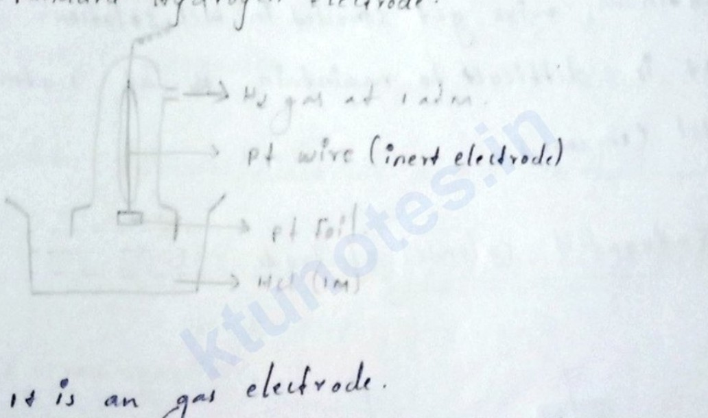
Diagram of Standard Hydrogen Electrode (SHE)

=> It is an gas electrode.

=> H2H_2 gas at 1 atm is bubbled through a platinum wire which is connected to a platinum foil. These are immersed in 1 molar HClHCl solution at 298K298K.

=> When SHE electrode as anode - (oxn occur)(ox^n \text{ occur})

H2(g)⟶2H(aq)++2e−H_{2 (g)} \longrightarrow 2H^+_{(aq)} + 2e^-

=> When SHE as cathode - (redn occur)(red^n \text{ occur}).

2H(aq)++2e−⟶H2(g)2H^+_{(aq)} + 2e^- \longrightarrow H_{2 (g)}


Page 53 of 105

=> Electrode representation:

H+/H2/PtH^+/H_2/Pt

=> ESHE∘=0 VE^\circ_{SHE} = 0\text{ V}, EH+/H2∘=0 VE^\circ_{H^+/H_2} = 0\text{ V}.

Limitations of SHE

=> Platinum wire get corroded in HCl\text{HCl} solution. => It is difficult to maintain H2H_2 at 1 atm1\text{ atm} and HCl\text{HCl} (1 M conc.1\text{ M conc.}).

Saturated calomel electrode.

Diagram of a saturated calomel electrode showing mercury, platinum wire, KCl solution, and outer glass jacket with side arms.

=> It is metal salt ion electrode having common anion => Hg2Cl2\text{Hg}_2\text{Cl}_2 (mercurous chloride). Also called as calomel.


Page 54 of 105

solution.

⇒\Rightarrow It contains 0.10.1 normal HCl\text{HCl}, Ag|AgCl\text{Ag|AgCl} electrode and special type of glass bulb with high [uncertain: electrical] conductance.

⇒\Rightarrow Glass bulb is made up of [uncertain: soda] SiO2,Al2O3\text{SiO}_2, \text{Al}_2\text{O}_3, [uncertain: CaO]

⇒\Rightarrow Based on the percentage composition of the components electrode potential will be different.

  • Electrode reaction

H++1e⟶12H2H^+ + 1e \longrightarrow \frac{1}{2} H_2

  • Nernst equation =

Eglass=Eglass∘+0.05911log⁡[H+]E_{\text{glass}} = E_{\text{glass}}^{\circ} + \frac{0.0591}{1} \log [H^+]

  • pH=−log⁡H+\text{pH} = -\log H^+

Eglass=Eglass∘−0.0591 pH\boxed{E_{\text{glass}} = E_{\text{glass}}^{\circ} - 0.0591 \text{ pH}}


Page 55 of 105

  • Electrode representation.

glass∣0.1 M HCl∣Ag - AgCl\text{glass} \mid 0.1 \text{ M HCl} \mid \text{Ag - AgCl}

  • Determination of pH.

⇒\Rightarrow A cell is developed in which glass electrode dipped in unknown solution (pH to be determined) and is connected to a reference electrode. (SCE)
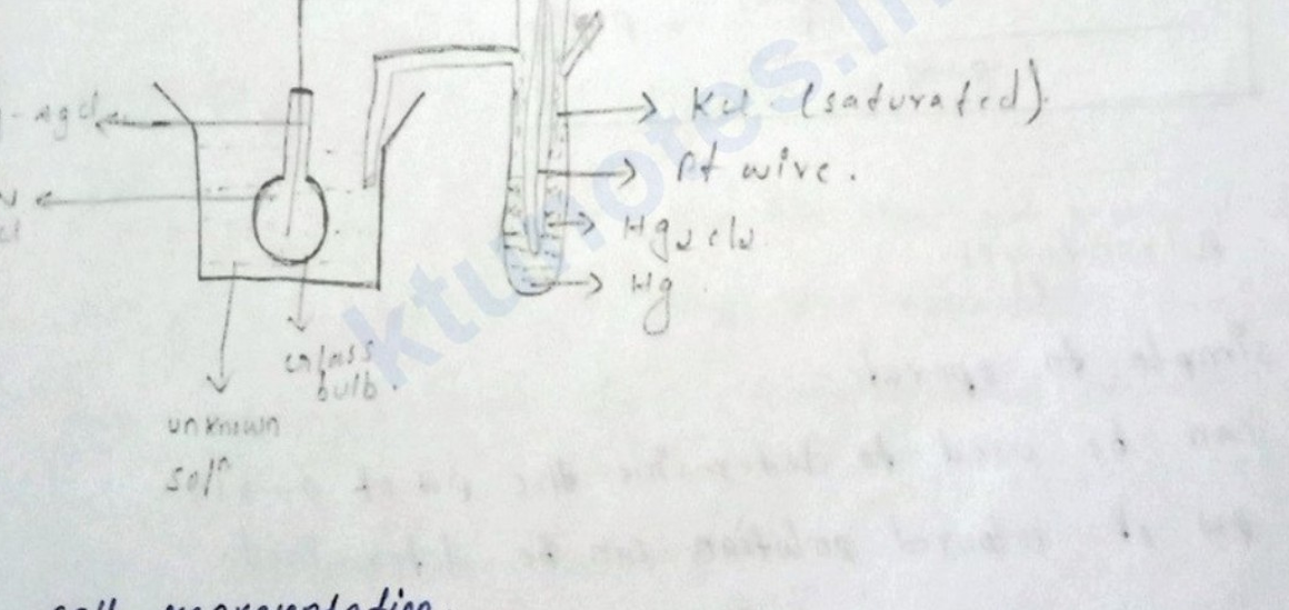
Diagram of experimental setup for determination of pH using a glass electrode and a reference electrode

  • Cell representation.

Ag - AgCl∣0.1 M HCl∣glass∣unknown soln⟶anode\text{Ag - AgCl} \mid 0.1 \text{ M HCl} \mid \text{glass} \mid \text{unknown sol}^n \longrightarrow \text{anode}

∥KCl(sat)∣Hg2Cl2/Hg∣Pt⟶cathode\parallel \text{KCl}_{(\text{sat})} \mid \text{Hg}_2\text{Cl}_2 / \text{Hg} \mid \text{Pt} \longrightarrow \text{cathode}


Page 56 of 105

calculation

Ecell=Ecathode−EanodeE_{cell} = E_{cathode} - E_{anode}

Ecell=Esec−EglassE_{cell} = E_{sec} - E_{glass}

Ecell=0.2422−[Eglass0−0.0591pH]E_{cell} = 0.2422 - \left[E^0_{glass} - 0.0591 pH\right]

Ecell=0.2422−Eglass0+0.0591pHE_{cell} = 0.2422 - E^0_{glass} + 0.0591 pH

Ecell−0.2422+Eglass0=0.0591pHE_{cell} - 0.2422 + E^0_{glass} = 0.0591 pH

Ecell−0.2422+Eglass00.0591=pH\frac{E_{cell} - 0.2422 + E^0_{glass}}{0.0591} = pH

⟶\longrightarrow Advantages:

  • simple to operate.
  • can be used to determine the pH of 0⟶100 \longrightarrow 10.
  • pH of coloured solution can be determined.

⟶\longrightarrow Disadvantage

  • cannot be used for determination of the pH 11⟶1411 \longrightarrow 14.

Page 57 of 105

Battery

  • Battery & fuel cell.

=> primary battery or cell.

Electrode or electrode reaction cannot be reversed by applying electricity. They are irreversible in nature. After the single usage it become dead.

eg: Dry cell, Daniel cell

=> secondary battery / Reversible battery.

Electrode or electrode reaction can be reversed by applying electricity. They are reversible. can we use multiple time by charging and discharging.

eg: Lithium ion battery.

=> Fuel cells.

In Fuel cells reactants, products, and electrolytes are continously passing through the cell by this chemical energy converted to electrical energy.

eg: H2−O2H_2-O_2 fuel cell.


Page 58 of 105

Lithium Ion battery imp.

=> It is a secondary battery or reversible battery => Electrode reaction can be reversed by applying electrical energy. => Li+\text{Li}^+ ions are responsible for charging & discharging, it is a light weight metal ion. => Following components are involved in lithium ion battery.

  1. -ve electrode = graphite (C)_{(C)} or lithiated graphite (Li)_{(Li)}.
  2. +ve electrode = Lithium metal oxide. eg: LiCoO2\text{LiCoO}_2
  3. An electrolyte - For the movement of Li+\text{Li}^+ ions. eg: LiPF6\text{LiPF}_6.
  4. A separator between positive & -ve electrode. eg - polymer gels are used.

Page 59 of 105

charging (electrolytic cell).
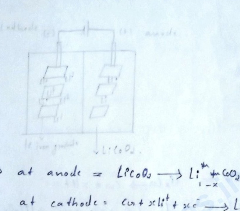
Diagram of an electrolytic cell for charging a lithium-ion battery

⇒\Rightarrow at anode =LiCoO2⟶Li1−xCoO2+xLi++xe−= \text{LiCoO}_2 \longrightarrow \text{Li}_{1-x}\text{CoO}_2 + x\text{Li}^+ + x\text{e}^- (oxn)

⇒\Rightarrow at cathode =C6+xLi++xe−⟶LixC6= \text{C}_6 + x\text{Li}^+ + x\text{e}^- \longrightarrow \text{Li}_x\text{C}_6

⇒\Rightarrow overall reaction =LiCoO2+C6⟶Li1−xCoO2+LixC6= \text{LiCoO}_2 + \text{C}_6 \longrightarrow \text{Li}_{1-x}\text{CoO}_2 + \text{Li}_x\text{C}_6

→\rightarrow During charging Li+\text{Li}^+ ion battery act as electrolytic cell.

⇒\Rightarrow Li+\text{Li}^+ ions flows from +ve→−ve+\text{ve} \rightarrow -\text{ve} electrode through the electrolyte and deposited as LixC6\text{Li}_x\text{C}_6 (lithiated graphite)

⇒\Rightarrow By which Co3+\text{Co}^{3+} is oxidise to Co4+\text{Co}^{4+} ions.


Page 60 of 105

Discharging. (electrochemical cell)
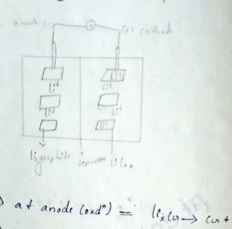
Diagram of an electrochemical cell during discharging showing anode, cathode, separator, voltmeter, and lithium insertion in graphite and LiCoO2

=> at anode (oxdnoxd^n) == LixC→C+xLi++xe−\text{Li}_x\text{C} \rightarrow \text{C} + x\text{Li}^+ + x\text{e}^-

=> at cathode (rednred^n) == Li1−xCoO2+xLi++xe−→LiCoO2\text{Li}_{1-x}\text{CoO}_2 + x\text{Li}^+ + x\text{e}^- \rightarrow \text{LiCoO}_2

=> Overall reaction == Li1−xCoO2+LixC→LiCoO2+xC\text{Li}_{1-x}\text{CoO}_2 + \text{Li}_x\text{C} \rightarrow \text{LiCoO}_2 + x\text{C}

=> During discharging Li+\text{Li}^+ ion battery act as electrochemical cell.

=> Li+\text{Li}^+ ion flow back to the +ve+ve electrode, through the electrolyte and form LiCoO2\text{LiCoO}_2.

=> The movement of lithium ions through the electrolytes are responsible for charging & discharging.


Page 61 of 105

Definition & working.

⇒\Rightarrow A H2−O2\text{H}_2 - \text{O}_2 Fuel cell is an electrochemical device that convert chemical energy to electrical energy.

⇒\Rightarrow Hydrogen gas is fed into the anode.

⇒\Rightarrow oxygen gas is fed into the cathode.

⇒\Rightarrow The electrons flowing from the anode to the cathode through an external circuit, generate electricity.

Merit's & demerit's of H2−O2\text{H}_2 - \text{O}_2 Fuel cell.

merits

→\rightarrow zero emissions

→\rightarrow high efficiency

→\rightarrow low noise

→\rightarrow Fuel flexibility.

Demerits

→\rightarrow High cost.

→\rightarrow durability

→\rightarrow storage and handling.


Page 62 of 105

Conductance, conductivity, & measurement of conductivity

⇒\Rightarrow write the definition equation & unit of the following

(1) Resistance.

(2) Resistivity / specific resistance.

(3) conductance.

(4) conductivity / specific conductance.

⇒\Rightarrow Resistance ⇒\Rightarrow It is the measure of the opposition to the flow of current in an electrical circuit.

⇒R=V/I\Rightarrow R = V/I (Ω\Omega)

⇒\Rightarrow Resistivity ⇒\Rightarrow It is a property of a material that quantifies it's intrinsic ability to oppose the flow of electric current.

⇒ρ=R⋅A/l\Rightarrow \rho = R \cdot A/l (Ωcm\Omega \text{cm})

⇒\Rightarrow conductance ⇒\Rightarrow It is a materials ability to allow the flow of electric charge or heat through it.

⇒C=1R\Rightarrow C = \frac{1}{R} (Ω−1\Omega^{-1}, siemens)

⇒\Rightarrow conductivity ⇒\Rightarrow The property of a material to allow the flow of electricity through it.

⇒κ=1ρ=1R⋅lA\Rightarrow \kappa = \frac{1}{\rho} = \frac{1}{R} \cdot \frac{l}{A} (S/m)


Page 63 of 105

Note ⇒\Rightarrow

  • C=1R−C=C = \frac{1}{R} - \quad C = conductance, R=R = Resistance.

  • R=ρla=ρ=R = \rho \frac{l}{a} = \quad \rho = specific resistance, l=l = length, a=a = area.

  • k=1ρ=k=k = \frac{1}{\rho} = \quad k = conductivity, ρ=\rho = resistivity.

  • ρ=R×al=unit=Ω(cm2cm)=Ωcm\rho = R \times \frac{a}{l} = \quad \text{unit} = \Omega \left(\frac{\text{cm}^2}{\text{cm}}\right) = \Omega \text{cm}

  • k=1R×al=1R×la=Ω−1cm−1=Scm−1k = \frac{1}{R \times \frac{a}{l}} = \frac{1}{R} \times \frac{l}{a} = \Omega^{-1} \text{cm}^{-1} = \text{S} \text{cm}^{-1}

  • calculate the specific conductance. The resistance of 0.1N0.1 \text{N} solution of a salt contain in a volume between two electrodes, 4cm4 \text{cm} apart and 10cm210 \text{cm}^2 in area was found to be 70  Ω70 \; \Omega.

A) k=1ρ=1R×la\quad k = \frac{1}{\rho} = \frac{1}{R} \times \frac{l}{a}


Page 64 of 105

==10.170×410.7=5.94×10⁻³ S cm−1=\begin{aligned} &= \frac{1}{0.170} \times \frac{4}{10.7} \\ &= 5.94 \times 10^{-3} \text{ S cm}^{-1} \end{aligned}

→\rightarrow Measurement of conductivity using digital conductivity meter.

  • Conductivity of any solution can be measured using digital conductivity meter.

conductivity of a solution=conductance of that soln×cell constant\text{conductivity of a solution} = \text{conductance of that soln} \times \text{cell constant}

cell constant=conductivity of KClconductance of KCl\text{cell constant} = \frac{\text{conductivity of KCl}}{\text{conductance of KCl}}

⇒\Rightarrow conductivity of 0.10.1 molar KCl\text{KCl}

Temperature (∘C^{\circ}\text{C})conductivity (mS cm−1\text{mS cm}^{-1})
2713.35
2813.59
2913.84
3014.09
3114.34

Page 65 of 105

Electrochemistry & Corrosion

→\rightarrow Corrosion is the disintegration of metal by chemical or electrochemical reaction with the environment.

eg: Rusting of iron, tarnishing of silver etc...

→\rightarrow Course of corrosion →\rightarrow Most of the metal exist in as it's combined form such as oxide, carbonate, sulphate etc...

→\rightarrow Extraction of metal from it's combined form needs special metallurgical processes. [Simply combined forme is more stable than free state].

→\rightarrow Every metal will have a tendency to revert back to it's stable state - corrosion.

→\rightarrow Some metals like gold, platinum will exist in elemental state in nature have excellent corrosion resistance.


Page 66 of 105

Galvanic series.

→\rightarrow It provides informations regarding reactivity of metals.

→\rightarrow It doesn't provide information in predicting corrosion behaviour.

→\rightarrow Metals having low reduction potential are anionic and undergo reduction faster.

→\rightarrow Galvanic series is a series in which metals and alloys are arranged in order of their corrosion tendency.

→\rightarrow Series - \begin{tabular}{ll} \begin{tabular}{l} Mg \ Zn, \ Al \ Cd \ [illegible] \ cast iron \ solder. \end{tabular}} anionic & \begin{tabular}{l} Pt \ Cu \ Au \ Ti \ Ag \end{tabular}} cathodic. \end{tabular}

→\rightarrow Why zinc is more corronic than aluminium & silver is more corronic than titanium.

A) It is expected that Ti is corrodes faster than Ag, but Ti is less reactive than Ag. also Al above Zn is found to be less reactive than Zn. This is because Ti and Al develops a highly


Page 67 of 105

protective oxides film on their surface and hence their effective E∘E^{\circ} is more positive.

  • comparison of galvanic series & electrochemical series:
Galvanic serieselectrochemical series
⇒\Rightarrow E∘E^{\circ} is measured for metals and alloys.⇒\Rightarrow E∘E^{\circ} is measured for metals and non-metals.
⇒\Rightarrow E∘E^{\circ} is measured by dipping metals and alloys in unpolluted sea water.⇒\Rightarrow E∘E^{\circ} is measured by dipping pure metals in their 1M1M solution.
⇒\Rightarrow calomel electrode is used as reference electrode.⇒\Rightarrow SHE is used as reference electrode.
⇒\Rightarrow position of metal and alloy may change it predicts the relative corrosion tendencies.⇒\Rightarrow position of a metal is fixed. It predicts the relative displacement tendencies.

Page 68 of 105

EFe2+/Fe∘=−0.04 VE_{\text{Fe}^{2+}/\text{Fe}}^\circ = -0.04\text{ V}

EZn2+/Zn∘=−0.76 VE_{\text{Zn}^{2+}/\text{Zn}}^\circ = -0.76\text{ V}

ECu2+/Cu∘=0.34 VE_{\text{Cu}^{2+}/\text{Cu}}^\circ = 0.34\text{ V}

EAg+/Mg∘=0.80 VE_{\text{Ag}^+/\text{Mg}}^\circ = 0.80\text{ V}

Acid medium (EH+/H2∘=0 VE^{\circ}_{H^+/H_2} = 0\text{ V}).

⇒\Rightarrow Al, Fe, Zn can involve in corrosion because their E∘E^\circ value is more negative than 0 V0\text{ V}.

2Al+6HCl⟶2AlCl3+3H22\text{Al} + 6\text{HCl} \longrightarrow 2\text{AlCl}_3 + 3\text{H}_2

⇒\Rightarrow In the case of iron, FeCl2\text{FeCl}_2 is formed instead of FeCl3\text{FeCl}_3, because EFe2+/Fe∘E^\circ_{\text{Fe}^{2+}/\text{Fe}} is more negative than EFe3+/Fe∘E^\circ_{\text{Fe}^{3+}/\text{Fe}}.

Fe+2HCl⟶FeCl2+H2.\text{Fe} + 2\text{HCl} \longrightarrow \text{FeCl}_2 + \text{H}_2.

⇒\Rightarrow [illegible] Cu2+/Cu\text{Cu}^{2+}/\text{Cu} no reaction. Cannot involve in reaction.


Page 69 of 105

  1. Hydrogen evolution reaction in alkaline medium

→\to It takes place when metal is immersed in alkaline medium.

→\to Alkaline medium EH2/OH−∘=−0.828 VE^\circ_{H_2/OH^-} = -0.828\text{ V}.

Predict the corrosion behaviour of the following metal in the alkaline medium. Al, Fe, Zn, Cu, Ag

  1. Al can only involve in corrosion.

reaction at anode →\to Al⟶Al3++3e−\text{Al} \longrightarrow \text{Al}^{3+} + 3e^-.

reaction at cathode →\to 2H2O+2e−⟶H2+2OH−2\text{H}_2\text{O} + 2e^- \longrightarrow \text{H}_2 + 2\text{OH}^-

EH2/OH∘=−0.828 VE^\circ_{H_2/OH} = -0.828\text{ V}.

Write the cathodic & anodic reaction of electrochemical corrosion of zinc in acid medium.

A). reaction at anode →\to Zn⟶Zn2++2e−\text{Zn} \longrightarrow \text{Zn}^{2+} + 2e^-.

reaction at cathode →\to 2H++2e−⟶H22\text{H}^+ + 2e^- \longrightarrow \text{H}_2.

Zn+2H+⟶Zn2++H2\text{Zn} + 2\text{H}^+ \longrightarrow \text{Zn}^{2+} + \text{H}_2

(3) oxygen absortion corrosion in acid medium - →\to Rusting of Iron.


Page 70 of 105

Why do iron rods in uncontaminated concrete resist corrosion?

The cement creates a highly alkaline environment, which forms a protective passive oxide layer on the steel surface.

Corrosion prevention techniques

flowchart TD C["Corrosion prevention"] --> P["Cathodic protection"] C --> E["Electroplating"] C --> L["Electroless plating"] P --> S["Sacrificial anode method"] P --> I["Impressed current method"]

Sacrificial anode protection

The metallic structure to be protected, such as an underground pipeline, cable or ship hull, is connected by a wire to a more anodic metal.

The explanation continues on the next source page.


Page 71 of 105

anodic metal sacrifices and undergoes corrosion. Metals like MgMg, ZnZn and AlAl and their alloys are used as sacrificial anodes.
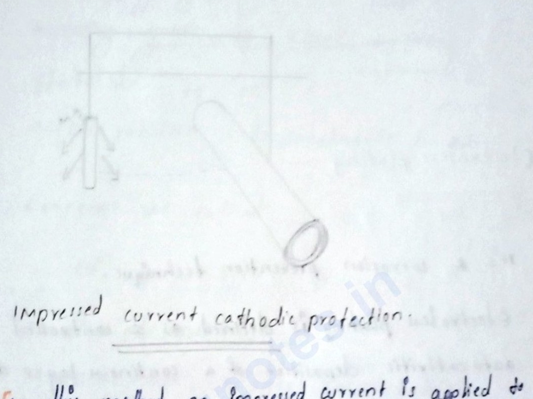
Diagram showing sacrificial anode connected to a metal structure

Impressed current cathodic protection:

In this method an impressed current is applied to convert the corroding metal from anode to cathode. A direct current from a DC source is applied to an anode which is buried inside the soil and to the corroding metal surface structure to be protected. A DC voltage applied such the corrosion current becomes zero or -ve. Ships docked in harbour are protected by this method.


Page 72 of 105
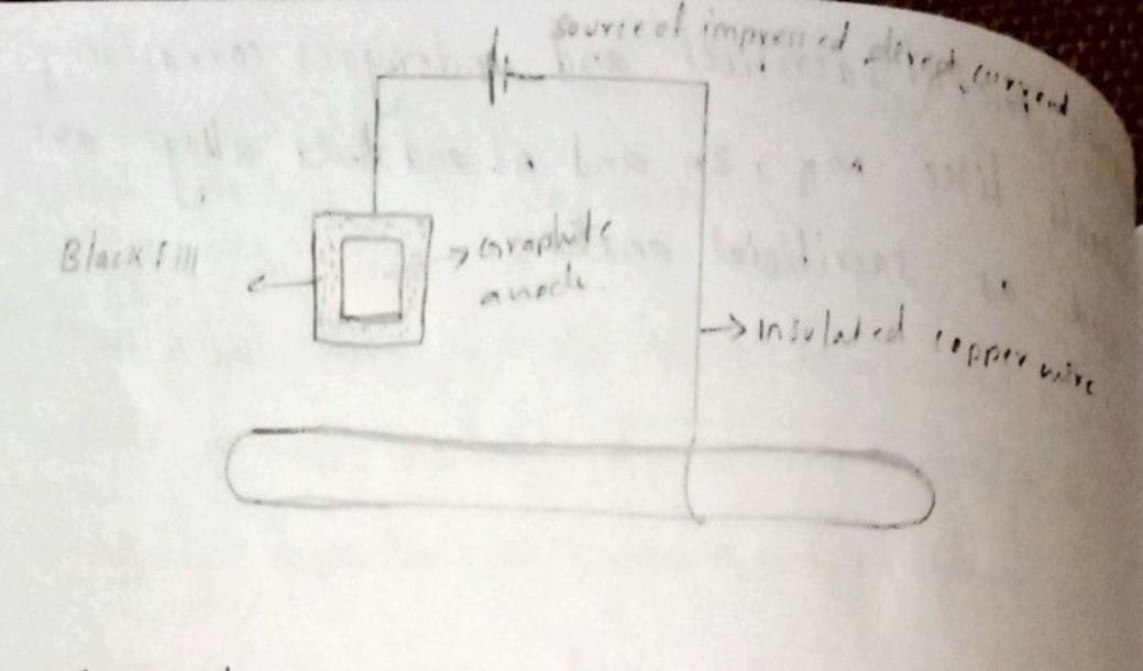
Schematic diagram of an electrochemical setup showing a power source, graphite anode, insulated copper wire, and a workpiece immersed in a bath.

Electroless plating

⇒\Rightarrow It's a corrosion prevention technique.

⇒\Rightarrow Electroless plating is defined as a controlled autocatalytic deposition of a continuous layer of a noble metal from it's salt solution on a surface of the base material by using suitable reducing agent without using electricity.

⇒\Rightarrow This method allow's the easy preparation of thin films using simple equipment.

⇒\Rightarrow The stability of electroless plating depends on the substrate material pree treatment method, type of soln\text{sol}^n used, pH\text{pH} of the material and temperature.


Page 73 of 105

  ⟹  \implies uses.

  • Prevent corrosion.

Electroplating of copper

  ⟹  \implies It is the process of depositing a layer of metal over the surface of another metal by passing electricity.

  ⟹  \implies It can be used for corrosion prevention method and for decoration purposes. In this method metal to be coated is taken as cathode.

  ⟹  \implies Electrolyte as copper sulphate solution.

  ⟹  \implies copper rod as anode.


Page 74 of 105

=> Reaction at anode

Cu⟶Cu2++2e−\text{Cu} \longrightarrow \text{Cu}^{2+} + 2\text{e}^{-}

=> Reaction at cathode.

Cu2++2e−⟶Cu\text{Cu}^{2+} + 2\text{e}^{-} \longrightarrow \text{Cu}

Electrolytic cell diagram for copper plating on an iron object

=> Advantages & disadvantages.

  1. Advantages

=> used for corrosion prevention.

=> used for decoration purpose.

  1. disadvantages

=> using electricity.

Page 75 of 105

[Non-content page]


Page 76 of 105

Module - 1

Electrochemistry and Corrosion

ELECTROCHEMISTRY : It is the branch of chemistry which deals with conversion of chemical reaction to electrical energy or convert electrical energy to chemical energy.

CELL : Device which consists of electrodes, suitable electrolyte, voltmeter and salt bridge.

TYPES OF CELL :

  1. ELECTROCHEMICAL CELL
  2. ELECTROLYTIC CELL

COMPARISON BETWEEN ELECTROCHEMICAL AND ELECTROLYTIC CELL.

ELECTROCHEMICAL CELLELECTROLYTIC CELL
→\rightarrow convert chemical energy to electrical energy.→\rightarrow converts electrical energy to chemical energy.
→ΔG=−ve\rightarrow \Delta G = -ve→ΔG=+ve\rightarrow \Delta G = +ve
→EMF=+ve\rightarrow \text{EMF} = +ve→EMF=−ve\rightarrow \text{EMF} = -ve
→Anode is −ve\rightarrow \text{Anode is } -ve→Anode is +ve\rightarrow \text{Anode is } +ve
→Eg: Daniel cell\rightarrow \text{Eg: Daniel cell}→Eg: Electroplating.\rightarrow \text{Eg: Electroplating.}

Page 77 of 105

Daniel cell diagram showing zinc rod in ZnSO4, copper rod in CuSO4, connected by a voltmeter and salt bridge.

REACTIONS:

  • Zn\text{Zn} acts as anode and readily lose two electrons and convert to Zn2+\text{Zn}^{2+}.

Zn⟶Zn2++2e−\text{Zn} \longrightarrow \text{Zn}^{2+} + 2\text{e}^-

  • Cu\text{Cu} acts as cathode. Cu2+\text{Cu}^{2+} ions from solution of CuSO4\text{CuSO}_4 take up 2e−2\text{e}^- from anode and reduce to Cu\text{Cu}.

Cu2++2e−⟶Cu\text{Cu}^{2+} + 2\text{e}^- \longrightarrow \text{Cu}

  • Overall reaction products:
\text{Zn} &\longrightarrow \text{Zn}^{2+} + 2\text{e}^- \\ \text{Cu}^{2+} + 2\text{e}^- &\longrightarrow \text{Cu} \hline \text{Zn} + \text{Cu}^{2+} &\longrightarrow \text{Zn}^{2+} + \text{Cu} \end{aligned}$ * $E_{\text{cell}} = 1.1\text{ V}$ $\begin{aligned} &= E_{\text{cathode}} - E_{\text{anode}} \\ &= E_{\text{Cu}^{2+}} - E_{\text{Zn}^{2+}} \\ &= 0.34 - (-0.76) \\ &= 1.1\text{ V} \end{aligned}$ SALT BRIDGE: It is an inverted $\text{U}$-shaped tube filled with gelatin or agar-agar and concentrated solution of inert electrolyte like $\text{KCl}$, $\text{KNO}_3$, $\text{NH}_4\text{NO}_3$, etc ---

Page 78 of 105

FUNCTIONS:

  • completes electrical neutrality circuit
  • maintains electrical neutrality.
  • minimise liquid junction potential:
    • junction potential : Potential difference set up across the junction of two solutions of electrolytes when these are in direct contact of each other.

SINGLE ELECTRODE POTENTIAL:
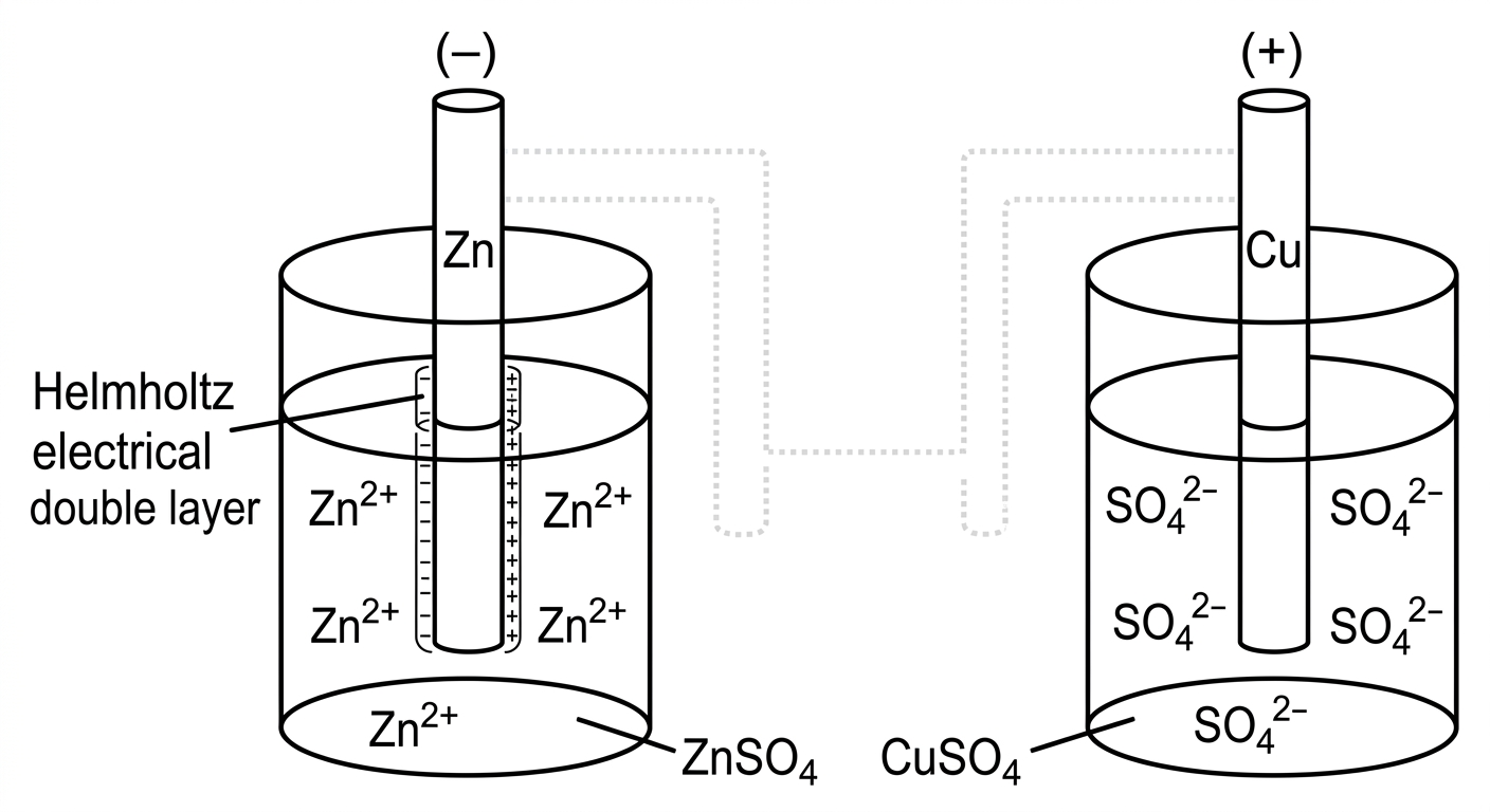
Diagram showing single electrode potentials for Zinc and Copper half-cells with Helmholtz electrical double layer

When a metal is in contact with its own salt solution, it may undergo oxidation or reduction depending on its nature. Due to these reactions, metal attracts opposite charged ions from the solution. These ions create a layer around the metal. This layer is known as Helmholtz electrical double layer. This layer develope a potential difference between metal and solution. At equilibrium, this potential difference becomes a constant value. This is known as single electrode potential. It measures tendency of a metal to lose or gain electron

STANDARD ELECTRODE POTENTIAL:

Electrode potential is measured under standard conditions (298 K, 1M electrolytic solution, 1 atm pressure) relative to standard hydrogen electrode (SHE) is called standard electrode potential.


Page 79 of 105

Ecell0=Ecathode0−Eanode0E_{cell}^0 = E_{cathode}^0 - E_{anode}^0

Ecell0=ESHE0−EZn0E_{cell}^0 = E_{SHE}^0 - E_{Zn}^0

=0−EZn0= 0 - E_{Zn}^0

EZn0=−Ecell0E_{Zn}^0 = -E_{cell}^0

=−0.76V= -0.76\text{V}

Q. Draw a neat sketch of Zn/Zn2+∥Ag+/Ag\text{Zn} / \text{Zn}^{2+} \parallel \text{Ag}^+ / \text{Ag} cell. Write chemical reactions. Find standard EMF (Ecell0E_{cell}^0) given that EZn0=−0.76VE_{\text{Zn}}^0 = -0.76\text{V}; EAg0=0.80VE_{\text{Ag}}^0 = 0.80\text{V}

Daniel cell sketch with Zn anode and Ag cathode

Anode: Zn⟶Zn2++2eˉ\text{Anode: } \text{Zn} \longrightarrow \text{Zn}^{2+} + 2\bar{e}

Cathode: 2Ag++2eˉ⟶2Ag\text{Cathode: } 2\text{Ag}^+ + 2\bar{e} \longrightarrow 2\text{Ag}

Overall reaction: Zn+2Ag+⟶Zn2++2Ag\text{Overall reaction: } \text{Zn} + 2\text{Ag}^+ \longrightarrow \text{Zn}^{2+} + 2\text{Ag}

Ecell0=EAg0−EZn0E_{cell}^0 = E_{\text{Ag}}^0 - E_{\text{Zn}}^0

=0.8−(−0.76)= 0.8 - (-0.76)

=1.56V= 1.56\text{V}

NERNST EQUATION:

Ecell=Ecell0−2.303RTnFlog⁡1[Mn+]E_{cell} = E_{cell}^0 - \frac{2.303RT}{nF} \log \frac{1}{[\text{M}^{n+}]}

Nernst derived an expression for single electrode potential is known as Nernst equation. This equation relates electrode potential and concentration of the solution.


Page 80 of 105

DERIVATION OF NERNST EQUATION:
consider a general reduction reaction.
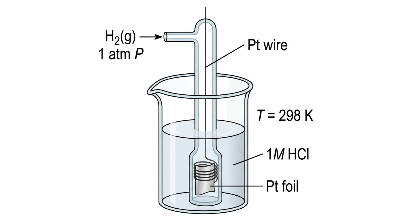
#x27; in math mode at position 19: …tleftharpoons M$̲$ For a rever…" style="color:#cc0000">ightleftharpoons M$ For a reversible reaction, free energy change ($ ext{ extDelta}G$) and equilibrium constant ($K$) are related as $ ext{ extDelta}G = ext{ extDelta}G^ ext{o} + RT ext{ ln } K ext{ — ① } ( ext{Vant Hoff's reaction isotherm})$ $ ext{ extDelta}G^ ext{o} ightarrow$ standard free energy change $R ightarrow$ Gas constant ($8.314 ext{ J K}^{-1} ext{mol}^{-1}$) $T ightarrow$ temperature ($298 ext{ K}$) In reversible reaction, electrical energy is produced, at the expense of free energy decrease. That is, $ ext{ extDelta}G = -nF E_{ ext{cell}} ext{ — ②}$ $ ext{ extDelta}G^ ext{o} = -nF E_{ ext{cell}}^ ext{o} ext{ — ③}$ Substitute eq ② and ③ in eq ①. $-nFE_{ ext{cell}} = -nFE_{ ext{cell}}^ ext{o} + RT ext{ln}K$ Divide throughout the equation by $-nF$. $E_{ ext{cell}} = E_{ ext{cell}}^ ext{o} - rac{RT}{nF} ext{ ln } K ext{ — ⑤}$ $K = rac{[ ext{Product}]}{[ ext{Reactant}]}$ $= rac{[ ext{M}]}{[ ext{M}^{n+}]}$ $= rac{1}{[ ext{M}^{n+}]}$ $ herefore E_{ ext{cell}} = E_{ ext{cell}}^ ext{o} - rac{RT}{nF} ext{ ln } rac{1}{[ ext{M}^{n+}]} ext{ — ⑥}$ ---

Page 81 of 105

Ecell=Ecell0−2.303RTnFlog⁡1[Mn+]−(7)E_{cell} = E^0_{cell} - \frac{2.303 RT}{nF} \log \frac{1}{[M^{n+}]} \quad -(7)

n=no. of electrons involved in the reactionn = \text{no. of electrons involved in the reaction}

F=faraday constant (96500 C)F = \text{faraday constant } (96500 \text{ C})

Substitute the values of R,TR, T and FF in eq. (7)(7)

Ecell=Ecell0−2.303×8.314×298n×96500log⁡1[Mn+]E_{cell} = E^0_{cell} - \frac{2.303 \times 8.314 \times 298}{n \times 96500} \log \frac{1}{[M^{n+}]}

Ecell=Ecell0−0.0591nlog⁡1[Mn+]E_{cell} = E^0_{cell} - \frac{0.0591}{n} \log \frac{1}{[M^{n+}]}

DERIVATION OF NERNST EQUATION FOR DANIEL CELL:

Daniel cell reaction,

Zn+Cu2+⟶Zn2++Cu\text{Zn} + \text{Cu}^{2+} \longrightarrow \text{Zn}^{2+} + \text{Cu}

Ecell=Ec−EaE_{cell} = E_{c} - E_{a}

=ECu−EZn−(1)= E_{Cu} - E_{Zn} \quad -(1)

ECu=ECu0−2.303RTnFlog⁡1[Cu2+]−(2)E_{Cu} = E^0_{Cu} - \frac{2.303 RT}{nF} \log \frac{1}{[Cu^{2+}]} \quad -(2)

EZn=EZn0−2.303RTnFlog⁡1[Zn2+]−(3)E_{Zn} = E^0_{Zn} - \frac{2.303 RT}{nF} \log \frac{1}{[Zn^{2+}]} \quad -(3)

Substitute (2)(2) and (3)(3) in (1)(1).

Ecell=ECu0−2.303RTnFlog⁡1[Cu2+]−(EZn0−2.303RTnFlog⁡1[Zn2+])E_{cell} = E^0_{Cu} - \frac{2.303 RT}{nF} \log \frac{1}{[Cu^{2+}]} - \left(E^0_{Zn} - \frac{2.303 RT}{nF} \log \frac{1}{[Zn^{2+]}}\right)

Ecell=ECu0−EZn0−2.303RTnF(log⁡1[Cu2+]−log⁡1[Zn2+])E_{cell} = E^0_{Cu} - E^0_{Zn} - \frac{2.303 RT}{nF} \left(\log \frac{1}{[Cu^{2+}]} - \log \frac{1}{[Zn^{2+}]}\right)

=Ecell0−2.303RTnFlog⁡1[Cu2+]1[Zn2+]= E^0_{cell} - \frac{2.303 RT}{nF} \log \frac{\frac{1}{[Cu^{2+}]}}{\frac{1}{[Zn^{2+}]}}


Page 82 of 105

Ecell=Ecell0−2.303RTnFlog⁡[Zn2+][Cu2+]E_{cell} = E^0_{cell} - \frac{2.303RT}{nF} \log \frac{[Zn^{2+}]}{[Cu^{2+}]}

$E_{cell} = E^0_{cell} - \frac{0.0591}{n} \log \frac{[Zn^{2+}]}{[Cu^{2+}]}$|

APPLICATIONS OF NERNST EQUATION :

  1. EMF of the cell can be determined by NERNST Equation.
  2. pH of the solution can determined from EMF of cell.
  3. It can be used in the calculation of number of electrons involved in the reaction, as well as determination of equilibrium constant of a reaction.

Q. Calculate the single electrode potential of ZnZn at 25∘C25^\circ\text{C} and concentration of [Zn2+]=0.01M[Zn^{2+}] = 0.01\text{M} and EZn2+/Zn0=−0.76VE^0_{Zn^{2+}/Zn} = -0.76\text{V}.

  ⟹  Ecell=Ecell0−0.0591nlog⁡1[Mn+]\implies E_{cell} = E^0_{cell} - \frac{0.0591}{n} \log \frac{1}{[M^{n+}]}

Zn→Zn2++2e−Zn \rightarrow Zn^{2+} + 2e^{-} n=2n = 2

E_{cell} &= -0.76 - \frac{0.0591}{2} \log \frac{1}{0.01} \ &= -0.76 - \frac{0.0591}{2} \log 10^2 \ &= -0.76 - \frac{0.0591}{\cancel{2}} \times \cancel{2} \log 10 \ &= -0.76 - 0.0591 \ &= -0.8191\text{V} \end{aligned}$ ---

Page 83 of 105

Q. Calculate the EMF of a Daniel cell when the concentration of Zn2+=0.01M\text{Zn}^{2+} = 0.01\text{M} and concentration of Cu2+=0.1M\text{Cu}^{2+} = 0.1\text{M}; given that EZn2+/Zn0=−0.76VE^0_{\text{Zn}^{2+}/\text{Zn}} = -0.76\text{V} and ECu2+/Cu0=0.34VE^0_{\text{Cu}^{2+}/\text{Cu}} = 0.34\text{V}.

Ecell=Ecell0−0.0591nlog⁡[Zn2+][Cu2+]Ecell0=Ec0−Ea0=0.34−(−0.76)=1.1−0.05912log⁡(0.010.1)=1.1V=1.1−0.05912×−1=1.1+0.02955=1.12955V\begin{aligned} E_{\text{cell}} &= E^0_{\text{cell}} - \frac{0.0591}{n} \log \frac{[\text{Zn}^{2+}]}{[\text{Cu}^{2+}]} & E^0_{\text{cell}} &= E^0_{\text{c}} - E^0_{\text{a}} \\ & && = 0.34 - (-0.76)\\ &= 1.1 - \frac{0.0591}{2} \log \left(\frac{0.01}{0.1}\right) & &= 1.1\text{V}\\ &= 1.1 - \frac{0.0591}{2} \times -1 && \\ &= 1.1 + 0.02955 && \\ &= 1.12955\text{V} && \end{aligned}

Q. Write the cell reaction and cell representation of Cu−Ag\text{Cu}-\text{Ag} cell at 25∘C25^\circ\text{C}. Given that EAg+/Ag0=0.80VE^0_{\text{Ag}^+/\text{Ag}} = 0.80\text{V} and ECu2+/Cu0=0.34VE^0_{\text{Cu}^{2+}/\text{Cu}} = 0.34\text{V}. Calculate the EMF of the cell when concentration of Ag+=0.1M\text{Ag}^+ = 0.1\text{M} and [Cu2+]=0.01M[\text{Cu}^{2+}] = 0.01\text{M}.

⇒\Rightarrow

Cell reaction:

Cu+2Ag+⟶Cu2++2Ag\text{Cu} + 2\text{Ag}^+ \longrightarrow \text{Cu}^{2+} + 2\text{Ag} n=2n = 2 Cu⟶Cu2++2eˉ2Ag++2eˉ⟶2Ag\begin{aligned} \text{Cu} &\longrightarrow \text{Cu}^{2+} + 2\bar{e} \\ 2\text{Ag}^+ + 2\bar{e} &\longrightarrow 2\text{Ag} \end{aligned}

Cell representation:

Cu∣Cu2+∥Ag+∣Ag\text{Cu} \mid \text{Cu}^{2+} \parallel \text{Ag}^+ \mid \text{Ag} Ecell0=Ec0−Ea0=0.34−0.800.80−0.34=+0.46\begin{aligned} E^0_{\text{cell}} &= E^0_{\text{c}} - E^0_{\text{a}} \\ &= 0.34 - 0.80 \quad \cancel{0.80 - 0.34} \\ &= +0.46 \end{aligned}

Page 84 of 105

Ecell=Ecell0−0.0591nlog⁡[Cu2+][Ag+]2E_{cell} = E^0_{cell} - \frac{0.0591}{n} \log \frac{[Cu^{2+}]}{[Ag^+]^2}

=0.46−0.05912log⁡(0.01(0.1)2)= \cancel{0.46} - \frac{0.0591}{2} \log \left( \frac{0.01}{(0.1)^2} \right)

=0.046−0.02955×10= \cancel{0.046} - 0.02955 \times 10

=0.46  +0.02955= \cancel{0.46} \; \cancel{+ 0.02955}

=0.48955= \cancel{0.48955}

=0.46 V‾= \underline{0.46\text{ V}}

Q. Calculate the equilibrium constant of daniel cell reaction given that Ecell0=1.1 VE^0_{cell} = 1.1\text{ V}.

→Ecell=Ecell0−0.05912log⁡K\rightarrow E_{cell} = E^0_{cell} - \frac{0.0591}{2} \log K

At equilibrium, ΔG=0\Delta G = 0, Ecell=0E_{cell} = 0

log⁡K=Ecell−Ecell0−0.02955\log K = \frac{E_{cell} - E^0_{cell}}{-0.02955}

=−1.1−0.02955= \frac{-1.1}{-0.02955}

=1.10.02955= \frac{1.1}{0.02955}

=37.225‾= \underline{37.225}

K=e37.225 Antilog(37.225)K = \cancel{e^{37.225}} \text{ Antilog}(37.225)

=1.468×10¹⁶  1.67×1037‾= \cancel{1.468 \times 10^{16}} \; \underline{1.67 \times 10^{37}}

Q. Calculate single zinc electrode potential of zinc electrode when [Zn2+]=0.1 M[\text{Zn}^{2+}] = 0.1\text{ M} and temperature 50∘C50^\circ\text{C}.

$\rightarrow E_{cell} = E^0_{cell} - \frac{2.303 RT}{nF} \log \frac{1}{[\text{Zn}^{2+}]},, 50^\circ\text{C} = 323\text{ K}$[illegible]

=−0.76−2.303×8.314×503232×96500log⁡(10.1)= -0.76 - \frac{2.303 \times 8.314 \times \cancel{50}^{323}}{2 \times 96500} \log \left(\frac{1}{0.1}\right)


Page 85 of 105

#x27; in math mode at position 86: … 96500} \log 10$̲$$\begin{align…" style="color:#cc0000">= -0.76 - \frac{2.303 \times 8.314 \times \overset{323}{298}}{2 \times 96500} \log 10$$\begin{aligned} &= -0.76 - 0.032 \times 1 \ &= -0.792\text{V} \end{aligned}

REFERENCE ELECTRODES:

Reference electrodes are standard electrodes with which we can find out electrode potential of other electrodes. It is classified into two:

(i) Primary Reference electrode. (Eg: SHE or NHE (normal hydrogen electrode)) (ii) Secondary Reference electrode. (Eg: Calomel electrodes, glass electrodes)

CONSTRUCTION AND WORKING OF SHE:

Diagram of Standard Hydrogen Electrode (SHE)

↪\hookrightarrow The Hydrogen gas at 1 atm pressure is continuously bubbled into the solution. ↪\hookrightarrow The bubblesgas\underset{\text{gas}}{\text{bubbles}} in contact with the ions function as reversible electrodes.

WORKING:


Page 86 of 105

NERNST EQUATION OF SHE :

EH2=EH20−0.05912log⁡1[H+]2E_{H_2} = E^0_{H_2} - \frac{0.0591}{2} \log \frac{1}{[H^+]^2}

EMF of SHE is taken as zero at all temperature.

LIMITATIONS OF SHE :

Diagram of Calomel Electrode

  • Very difficult to set up SHE.
  • It requires considerable volume of electrolyte solution.
  • It cannot be used in redox systems.
  • It is readily affected by compounds of sulphur, compound mercury, and Arsenic, Fe3+Fe^{3+} ions, MnO4−MnO_4^-, etc.
  • It is difficult to maintain pressure of the gas, 1 atm1\text{ atm}, at concentration of the solution at 1 M1\text{ M}.

CALOMEL ELECTRODE :

CONSTRUCTION :

  • It is a secondary Reference electrode.
  • It belongs to metal - metal sparingly soluble salt electrode.
  • Calomel electrode consists of long glass tube having two side tubes on each side.
  • Hg metal is placed at the bottom of the glass tube.
  • Hg2Cl2Hg_2Cl_2 is coated on Hg & metal. (Sparingly soluble salt).
  • Saturated KCl solution is filled inside the glass tube.
  • Platinum wire with foil is dipped in that solution.

Page 87 of 105

Diagram of a Calomel Electrode showing its internal structure and labeling

WORKING :

  • If it acts as anode : 2Hg⟶Hg22++2e‾2Hg \longrightarrow Hg_2^{2+} + 2\overline{e} Hg22++2Cl−⟶Hg2Cl2Hg_2^{2+} + 2Cl^{-} \longrightarrow Hg_2Cl_2 \hline 2Hg+2Cl−⟶Hg2Cl2+2e‾2Hg + 2Cl^{-} \longrightarrow Hg_2Cl_2 + 2\overline{e}

  • If it acts as cathode : Hg22++2e‾⟶2HgHg_2^{2+} + 2\overline{e} \longrightarrow 2Hg Hg2Cl2⟶Hg22++2Cl−Hg_2Cl_2 \longrightarrow Hg_2^{2+} + 2Cl^{-} \hline Hg2Cl2+2e‾⟶2Hg+2Cl−Hg_2Cl_2 + 2\overline{e} \longrightarrow 2Hg + 2Cl^{-}

  • Representation of calomel electrode : Cl−∣Hg2Cl2∣HgCl^{-} | Hg_2Cl_2 | Hg

NERSNT EQUATION OF CALOMEL ELECTRODE : Ecalomel=Ecalomel∘−0.05912log⁡[Cl−]2E_{\text{calomel}} = E_{\text{calomel}}^{\circ} - \frac{0.0591}{2} \log [Cl^{-}]^2 =0.28422−0.05912×2log⁡[Cl−]= 0.28422 - \frac{0.0591}{2} \times 2 \log [Cl^{-}] Ecalomel=0.2422−0.0591log⁡[Cl−]E_{\text{calomel}} = 0.2422 - 0.0591 \log [Cl^{-}]


Page 88 of 105

CLASSIFICATION :

Calomel electrode is classified into 3 depending on the concentration of KCl\text{KCl}.

(i) Saturated Calomel electrode (SCE\text{SCE}) : →\rightarrow Saturated KCl\text{KCl} used as electrolyte. →EMF=0.2422V\rightarrow \text{EMF} = 0.2422 \text{V}

(ii) Normal calomel electrode (NCE\text{NCE}) : →1N KCl\rightarrow 1 \text{N KCl} →EMF=0.2810V\rightarrow \text{EMF} = 0.2810 \text{V}

(iii) Decinormal calomel electrode (DCE\text{DCE}) : →0.1N KCl\rightarrow 0.1 \text{N KCl} →EMF=0.3335V\rightarrow \text{EMF} = 0.3335 \text{V}

APPLICATION OF SCE\text{SCE} :

→\rightarrow To determine electrode potential of any electrode. Eg\text{Eg}: Determination of electrode potential of zinc electrode using SCE\text{SCE}. In order to measure electrode potential of Zn\text{Zn} electrode, zinc is dipped in 1M1 \text{M} zinc sulphate (ZnSO4\text{ZnSO}_4) solution and connected to SCE\text{SCE} through digit voltmeter.

Here, Zn\text{Zn} acts as anode and SCE\text{SCE} acts as cathode.

Experimental setup for determining the electrode potential of a Zn electrode using a Saturated Calomel Electrode (SCE)


Page 89 of 105

• Representation : Zn∣Zn2+∥Cl−∣Hg2Cl2∣Hg\text{Zn} \mid \text{Zn}^{2+} \parallel \text{Cl}^- \mid \text{Hg}_2 \text{Cl}_2 \mid \text{Hg}

• Anode : Zn⟶Zn2++2eˉ\text{Zn} \longrightarrow \text{Zn}^{2+} + 2\bar{e}

• Cathode : Hg2Cl2+2eˉ⟶2Hg+2Cl−\text{Hg}_2 \text{Cl}_2 + 2\bar{e} \longrightarrow 2\text{Hg} + 2\text{Cl}^- Zn+Hg2Cl2⟶Zn2++2Hg+2Cl−‾\overline{\text{Zn} + \text{Hg}_2 \text{Cl}_2 \longrightarrow \text{Zn}^{2+} + 2\text{Hg} + 2\text{Cl}^-}

Ecell=Ec−EaE_{\text{cell}} = E_c - E_a =ESCE−EZn2+/Zn= E_{\text{SCE}} - E_{\text{Zn}^{2+}/\text{Zn}} =0.2422−EZn2+/Zn= 0.2422 - E_{\text{Zn}^{2+}/\text{Zn}}

EZn2+/Zn=0.2422−EcellE_{\text{Zn}^{2+}/\text{Zn}} = 0.2422 - E_{\text{cell}}

• Determination of electrode potential of copper using SCE.

Diagram showing the experimental setup for the determination of electrode potential of copper using SCE

• Representation : Cl−∣Hg2Cl2∣Hg∥Cu2+∣Cu\text{Cl}^- \mid \text{Hg}_2 \text{Cl}_2 \mid \text{Hg} \parallel \text{Cu}^{2+} \mid \text{Cu}

• Anode : 2Hg+2Cl−⟶Hg2Cl2+2eˉ2\text{Hg} + 2\text{Cl}^- \longrightarrow \text{Hg}_2 \text{Cl}_2 + 2\bar{e}


Page 90 of 105

  • Cathode :
    Cu2++2eˉ→Cu\text{Cu}^{2+} + 2\bar{e} \rightarrow \text{Cu}
    \hline
    2Hg+2Cl−+Cu2+→Hg2Cl2+Cu2\text{Hg} + 2\text{Cl}^- + \text{Cu}^{2+} \rightarrow \text{Hg}_2\text{Cl}_2 + \text{Cu}

Ecell=Ec−EaE_{\text{cell}} = E_c - E_a
=ECu2+∣Cu−ESCE= E_{\text{Cu}^{2+}|\text{Cu}} - E_{\text{SCE}}
=ECu2+∣Cu−0.2422= E_{\text{Cu}^{2+}|\text{Cu}} - 0.2422

ECu2+∣Cu=Ecell+0.2422E_{\text{Cu}^{2+}|\text{Cu}} = E_{\text{cell}} + 0.2422

GLASS ELECTRODE:

CONSTRUCTION:

  • It is a secondary reference electrode
  • It belongs to ion selective electrode.
  • Ion selective electrode have the ability to respond to certain ions like H+,Na+,K+\text{H}^+, \text{Na}^+, \text{K}^+ and develops a potential
  • glass electrode is made up of corning glass.
  • corning glass is a combination of Na2O\text{Na}_2\text{O} (22%22\%), CaO\text{CaO} (6%6\%)andand\text{SiO}_2( (72%$).
  • \text{H} is widely used as \text{pH} meter.

Diagram of a glass electrode

  • glass electrode consists of a long glass tube with thin glass bulb.
  • The glass bulb is filled with 0.1M HCl0.1\text{M HCl}.
  • The inner surface of the glass is in contact with AgCl\text{AgCl} coated with Ag\text{Ag} wire or platinum wire.

Page 91 of 105

  • Representation: Ag∣AgCl∣0.1M HCl∣glass\text{Ag} \mid \text{AgCl} \mid 0.1\text{M HCl} \mid \text{glass}

  • EMF of glass electrode EG=EG∘−0.0591 pHE_G = E_G^\circ - 0.0591 \text{ pH} EG=EMF of the glass electrodeE_G = \text{EMF of the glass electrode} EG∘=standard EMF of the glass electrode (0.6 or 0.5)E_G^\circ = \text{standard EMF of the glass electrode} \ (0.6 \text{ or } 0.5)

APPLICATIONS:

  • Determination of pH of an unknown solution using glass electrode. In order to measure pH of an unknown solution, the glass electrode is directly dipped into that solution and connected to a SCE through digital voltmeter. Here, glass electrode act as cathode and SCE act as anode.

Experimental setup for determination of pH using a glass electrode and a saturated calomel electrode (SCE).

  • Representation: Cl−∣Hg2Cl2∣Hg∥Ag∣AgCl∣0.1M HCl∣glass∣unknown solution\text{Cl}^- \mid \text{Hg}_2\text{Cl}_2 \mid \text{Hg} \parallel \text{Ag} \mid \text{AgCl} \mid 0.1\text{M HCl} \mid \text{glass} \mid \text{unknown solution}

  • Ecell=Ec−EaE_{\text{cell}} = E_c - E_a =EG−ESCE= E_G - E_{\text{SCE}}


Page 92 of 105

Ecell=(EG0−0.0591 pH)−0.2422E_{cell} = (E_G^0 - 0.0591 \text{ pH}) - 0.2422 Ecell−EG0+0.2422=−0.0591 pHE_{cell} - E_G^0 + 0.2422 = -0.0591 \text{ pH} pH=−Ecell+EG0−0.24220.0591\text{pH} = \frac{-E_{cell} + E_G^0 - 0.2422}{0.0591}

CELL AND BATTERY

Battery is a combination of two or more cells.

TYPES:
  • PRIMARY CELL :

    • Cell reactions are irreversible.
    • Eg : Dry cell
  • SECONDARY CELL:

    • Cell reactions are reversible.
    • Eg : Lithium-ion Battery, Lead Acid Battery

LITHIUM-ION BATTERY :

Characteristics of Li :
  • Has higher negative value for reduction potential and lower atomic mass than any other metal.
Anode :

Lithium intercalated graphite (LixC)(\text{Li}_x\text{C})

Cathode :

Lithium ion inserted transition metal oxide (LiCoO2∣LiMnO2)(\text{LiCoO}_2 \mid \text{LiMn}\text{O}_2)

Electrolyte :

Lithium salt (LiBF4 or LiClO4)(\text{LiBF}_4 \text{ or } \text{LiClO}_4)

Discharging (voltaic cell) :
  • Anode : LixC⟶xLi++xe−+C\text{Li}_x\text{C} \longrightarrow x\text{Li}^+ + x\text{e}^- + \text{C}
  • Cathode : Li(1−x)CoO2+xLi++xe−⟶LiCoO2\text{Li}_{(1-x)}\text{CoO}_2 + x\text{Li}^+ + x\text{e}^- \longrightarrow \text{LiCoO}_2

Page 93 of 105

↳ Charging (Electrolytic cell):

↳ Anode: LiCoO2→Li(1−x)CoO2+xLi++xeˉ\text{LiCoO}_2 \rightarrow \text{Li}_{(1-x)}\text{CoO}_2 + x\text{Li}^+ + x\bar{e} ↳ Cathode: xLi++xeˉ+C→LixCx\text{Li}^+ + x\bar{e} + \text{C} \rightarrow \text{Li}_x\text{C}

Diagram of a Lithium-ion cell during charging

↳ APPLICATIONS: Used in mobiles, watches, digital cameras, etc.

↳ ADVANTAGES: ↳ Available in different size and shape. ↳ Light - weight. ↳ Good cycle stability. ↳ High energy density. ↳ Low self discharge rate.

Q Why Lithium-ion cell is not allowed to charge completely? Ans. When lithium-ion cells are allowed to charge completely, the anodic material (LiCoO2\text{LiCoO}_2) is converted to CoO2\text{CoO}_2 (cobalt oxide) which is an explosive material. Therefore, automatic built-in circuit breakers are inside the battery which allows charging only upto 90%.


Page 94 of 105

H2−O2\text{H}_2 - \text{O}_2 FUEL CELL (ACID ELECTROLYTE):

↳ Hydrogen fuel cell produces electricity based on following exothermic reaction.

2H2(g)+O2(g)⟶2H2O(l)2\text{H}_2(g) + \text{O}_2(g) \longrightarrow 2\text{H}_2\text{O}(l)

H2\text{H}_2 act as fuel and O2\text{O}_2 gas act as oxidant. So, it is known as H2−O2\text{H}_2 - \text{O}_2 fuel cell.

↳ CONSTRUCTION:

Diagram of H2-O2 Fuel Cell showing porous graphite electrodes, electrolyte, water outlet, and gas inlets.

↳ Fuel cell consist of two rows of porous graphite.

↳ Phosphoric acid (H3PO4{\text{H}_3\text{PO}_4}) is used as electrolyte.

↳ Hydrogen and Oxygen gas under 50 atm50\text{ atm} pressure is continously passed through anodic and cathodic compartments respectively.

↳ The cell operating temperature is maintained upto 200∘C200^\circ\text{C}.

↳ WORKING:

↳ Anode:

2H2(g)⟶4H++4eˉ(E=0V)2\text{H}_2(g) \longrightarrow 4\text{H}^+ + 4\bar{e} \quad (E = 0\text{V})

↳ Hydrogen gas is oxidised to H+\text{H}^+ ions and the electrons formed will flow to the anode through the external circuit.

↳ Cathode:

O2+4eˉ+4H+⟶2H2O(E=1.23V)\text{O}_2 + 4\bar{e} + 4\text{H}^+ \longrightarrow 2\text{H}_2\text{O} \quad (E = 1.23\text{V})

↳ Oxygen is getting reduced to water at the cathode by consuming H+\text{H}^+ ions from the electrolyte. H+\text{H}^+ ions deficiency at the electrolyte side is balanced by H+\text{H}^+ ions formed at anode.


Page 95 of 105

⌞\llcorner Overall Reaction : (E=1.23V)(E = 1.23 V) 2H2+O2⟶2H2O\text{2H}_2 + \text{O}_2 \longrightarrow \text{2H}_2\text{O}

⌞\llcorner APPLICATION : ↪\quad \hookrightarrow used in space crafts ↪\quad \hookrightarrow military applications ↪\quad \hookrightarrow stationary power generations.

⌞\llcorner ADVANTAGES : ↪\quad \hookrightarrow High efficiency : converts 80%80\% chemical energy to electrical energy. ↪\quad \hookrightarrow Doesn't cause any pollution. ↪\quad \hookrightarrow simple and easy to operate. ↪\quad \hookrightarrow It can supply energy continuously as long as reactants are fed. ↪\quad \hookrightarrow concentration of the electrolyte remains unchanged.

⌞\llcorner DISADVANTAGES : ↪\quad \hookrightarrow Expensive ↪\quad \hookrightarrow The electrolyte used is highly corrosive ↪\quad \hookrightarrow gaseous fuel are difficult to handle and store. ↪\quad \hookrightarrow Fuels used must be extremely pure.

CONDUCTIVITY :

CONDUCTORS :

Substance which allows the passage of electricity.

flowchart TD C[CONDUCTORS] --> EC[Electronic conductors] C --> ElC[Electrolytic conductors] EC --> EC1["charge carriers : electrons"] EC --> EC2["Eg: metal, semi conductors"] ElC --> ElC1["charge carriers : ions"] ElC --> ElC2["Eg: salt solutions, acid"]

RESISTANCE (R) : Resistance

Obstruction to the flow of current. Resistance of a conductor is directly proportional to length of conductor, and inversely proportional to area of cross section.


Page 96 of 105

R∝lAR \propto \frac{l}{A}

R=ρlAR = \frac{\rho l}{A}

ρ=RAl\rho = \frac{RA}{l}, $\rho = \text{Resistivity or specific resistance}$.

unit of R=ΩR = \Omega (ohms)

CONDUCTANCE (CC)

C=1RC = \frac{1}{R}

unit=Ω−1 or Siemen (S)\text{unit} = \Omega^{-1} \text{ or Siemen } (S)

SPECIFIC CONDUCTANCE OR CONDUCTIVITY (KK)

K=1ρK = \frac{1}{\rho}

=1RAl= \frac{1}{\frac{RA}{l}}

=lRA= \frac{l}{RA}, unit=S cm−1\text{unit} = S \text{ cm}^{-1}

conductivity=conductance×cell constant\text{conductivity} = \text{conductance} \times \text{cell constant}

=C×cell constant= C \times \text{cell constant}

CONDUCTIVITY CELL:

↪\hookrightarrow Consists of 2 rows of platinum welded with the end of platinum wire that are sealed in a glass tube. The rows are strongly fixed such that distance between electrodes remains unaltered.

Diagram of a conductivity cell showing a glass tube with two platinum rods (electrodes) connected to platinum wires.

unit of cell constant=cm−1\text{unit of cell constant} = \text{cm}^{-1}


Page 97 of 105

Measurement of conductivity of solution using digital conductivity meter.

conductivity cell is connected to the digital conductivity meter. conductivity cell is dipped into the sample solution taken in a beaker. Make sure that the cell is completely immersed in the solution. Measure the conductance of the solution by measuring proper range. Digital conductivity meter readily reads out the conductance.

conductivity of solution=C⋅cell constant\text{conductivity of solution} = C \cdot \text{cell constant}

Q. Calculate the conductivity of given sample of water at 298 K which shows a conductance of 560μS560\mu\text{S}. A standard solution of 0.1M KCl0.1\text{M KCl} shows a conductance of 12.34 mS12.34\text{ mS} in that cells, given that conductivity of 0.1M KCl0.1\text{M KCl} is 0.01288 S cm−10.01288\text{ S cm}^{-1}.

ans. Conductivity=Conductance×cell constant\text{Conductivity} = \text{Conductance} \times \text{cell constant}

cell constant=ConductivityConductance\text{cell constant} = \frac{\text{Conductivity}}{\text{Conductance}}

=0.01288 S cm−112.34×10⁻³ S= \frac{0.01288 \text{ S cm}^{-1}}{12.34 \times 10^{-3} \text{ S}}

=1.04376 cm−1= 1.04376 \text{ cm}^{-1}

water=C×cell constant\text{water} = C \times \text{cell constant}

=560×10−6×1.04376= 560 \times 10^{-6} \times 1.04376

=584.505×10⁻⁶ S cm−1= 584.505 \times 10^{-6}\text{ S cm}^{-1}


Page 98 of 105

CORROSION:

Corrosion is the degradation of metallic surface by chemical or electrochemical reaction with the environment.

4 TYPES:

flowchart TD C[corrosion] --> D[Dry corrosion] C --> W[Wet corrosion]
  • Dry corrosion
    1. Oxidation corrosion
    2. corrosion by gases
    3. Liquid metal corrosion
  • Wet corrosion
    1. Hydrogen evolution corrosion
    2. Oxygen absorption corrosion.

4 MECHANISM OF WET OR ELECTROCHEMICAL CORROSION:

  • It takes place under moist condition.
  • When the conducting liquid is in contact with the metal or two dissimilar metals are either inversed & immersed or partially dipped in a solution anode.
  • Oxidation occurs at the cathode. The metal oxidise to metal ion. M⟶Mn++neˉM \longrightarrow M^{n+} + n\bar{e}
  • Surrounding environment acts as anode cathode and reduce to non-metallic ions (OH−OH^- ions).
  • Diffusion of metallic ions and non-metallic ions towards each other and the formation of corrosion product.

WET CORROSION UNDER VARIOUS ENVIRONMENT CONDITION:

(i) HYDROGEN EVOLUTION CORROSION: IN ACIDIC MEDIUM:

  • Fe metal is immersed in a acidic solution:
  • Anode: Fe⟶Fe2++2eˉFe \longrightarrow Fe^{2+} + 2\bar{e} (E∘=−0.44VE^\circ = -0.44V) reduction potential
  • Cathode: 2H++2eˉ⟶H2(g)2H^+ + 2\bar{e} \longrightarrow H_2(g) (E∘=0VE^\circ = 0V)
  • The electrode potential of Fe is lower than electrode potential of hudmaon in acidic medium.

Page 99 of 105

(ii) HYDROGEN EVOLUTION CORROSION : IN ALKALINE MEDIUM : ( \hookrightarrow ) Anode: Al⟶Al3++3e‾(E∘=−1.66 V)\text{Al} \longrightarrow \text{Al}^{3+} + 3\overline{e} \quad (E^\circ = -1.66\text{ V}) ( \hookrightarrow ) Cathode: 2H2O+2e‾⟶H2(g)+2OH−(E∘=−0.828 V)2\text{H}_2\text{O} + 2\overline{e} \longrightarrow \text{H}_2(g) + 2\text{OH}^- \quad (E^\circ = -0.828\text{ V}) ( \hookrightarrow ) Electrode potential of Al ((-1.66\text{ V})) is lower than electrode potential of Hydrogen ((-0.828\text{ V})) in alkaline medium. Q. Why Fe doesn't corrode in alkaline medium by hydrogen evolution corrosion? ans. In alkaline medium, electrode potential of Fe is higher than electrode potential of hydrogen in alkaline

(iii) OXYGEN ABSORPTION CORROSION : IN ACIDIC MEDIUM : ( \hookrightarrow ) Anode: Fe⟶Fe2++2e‾(E∘=−0.44 V)\text{Fe} \longrightarrow \text{Fe}^{2+} + 2\overline{e} \quad (E^\circ = -0.44\text{ V}) ( \hookrightarrow ) Cathode: O2+4H++4e‾⟶2H2O(E∘=1.23 V)\text{O}_2 + 4\text{H}^+ + 4\overline{e} \longrightarrow 2\text{H}_2\text{O} \quad (E^\circ = 1.23\text{ V}) ( \hookrightarrow ) Fe metal is in contact with acidic medium containing sufficient amount of oxygen. ( \hookrightarrow ) Fe2+\text{Fe}^{2+} further oxidise to Fe3+\text{Fe}^{3+} because the reduction potential of Fe2+\text{Fe}^{2+} ((0.77\text{ V})) is lower than reduction potential of Oxygen electrode ((1.23\text{ V})) in acidic medium. Fe2+⟶Fe3++1e‾(E∘=0.77 V)\text{Fe}^{2+} \longrightarrow \text{Fe}^{3+} + 1\overline{e} \quad (E^\circ = 0.77\text{ V})

(iv) OXYGEN ABSORPTION CORROSION : IN ALKALINE MEDIUM : ( \hookrightarrow ) Anode: Fe⟶Fe2++2e‾(E∘=−0.44 V)\text{Fe} \longrightarrow \text{Fe}^{2+} + 2\overline{e} \quad (E^\circ = -0.44\text{ V}) ( \hookrightarrow ) Cathode: 2H2O+O2+2e‾⟶4OH−(E∘=0.40 V)2\text{H}_2\text{O} + \text{O}_2 + 2\overline{e} \longrightarrow 4\text{OH}^- \quad (E^\circ = 0.40\text{ V}) ( \hookrightarrow ) Electrode potential of Fe ((-0.44\text{ V})) is lower than electrode potential of oxygen ((0.40\text{ V})) in alkaline medium.


Page 100 of 105

[Non-content page]


Page 101 of 105

GALVANIC SERIES:

ightarrow ightarrow The series in which the metals and alloys are arranged in the decreasing order of their corrosion tendency.

ightarrow ightarrow A metal high in the series is more anodic and undergo corrosion easily.

Anodic{MgMg alloysZnAlCdCast ironSolderPbSnBrassCuNiStainless steelCrAgTiAuPt}Cathodic(easily(protected)corroded)\begin{matrix} \text{Anodic} & \left\{\begin{matrix} \text{Mg} \\ \text{Mg alloys} \\ \text{Zn} \\ \text{Al} \\ \text{Cd} \\ \text{Cast iron} \\ \text{Solder} \\ \text{Pb} \\ \text{Sn} \end{matrix}\right. & \left.\begin{matrix} \text{Brass} \\ \text{Cu} \\ \text{Ni} \\ \text{Stainless steel} \\ \text{Cr} \\ \text{Ag} \\ \text{Ti} \\ \text{Au} \\ \text{Pt} \end{matrix}\right\} & \text{Cathodic} \\ (\text{easily} & & & (\text{protected}) \\ \text{corroded}) & & & \end{matrix}

COMPARISON BETWEEN :

ELECTROCHEMICAL SERIESGALVANIC SERIES
↪\hookrightarrow E∘E^\circ is measured for metals and non-metals.↪\hookrightarrow E∘E^\circ is measured for metals and alloys.
↪\hookrightarrow Position of metal is fixed.↪\hookrightarrow The position of metal may change.
↪\hookrightarrow E∘E^\circ is measured by dipping metal in 1M1\text{M} salt solution.↪\hookrightarrow E∘E^\circ is measured by dipping metal in unpolluted sea water.
↪\hookrightarrow SHE is used as reference electrode↪\hookrightarrow Calomel electrode is used as reference electrode.
↪\hookrightarrow It can predict displacement tendency.↪\hookrightarrow It can predict corrosion tendency.

CATHODIC PROTECTION:

↪\hookrightarrow Principle of cathodic protection is to force the metal to be protected to behave as a cathode so that corrosion is prevented.


Page 102 of 105

CLASSIFIED INTO TWO:

(i) SACRIFICIAL ANODIC PROTECTION:

Diagram of sacrificial anodic protection showing a buried Fe pipe connected to a Mg anode.

→\rightarrow Underground metallic structures like cable, pipe, etc..., can be protected by this method. →\rightarrow Here, the metal to be protected is connected to more anodic metal through a wire. →\rightarrow So the anodic metal sacrifice and undergo corrosion. →\rightarrow Metals like Mg,Zn,Al,…\text{Mg}, \text{Zn}, \text{Al}, \dots are used as sacrificial anode.

(ii) IMPRESSED CURRENT CATHODIC PROTECTION:

Diagram of impressed current cathodic protection showing a DC power source connected to a graphite anode and a Fe pipe cathode.

→\rightarrow In this method an impressed current is applied to convert the corroding metal from anode to cathode. →\rightarrow A current from dc source is applied to an anode (inert material like graphite, platinum, stainless steel, etc) and to the corroding metal to be protected. When dc voltage is applied, corrosion current becomes zero. →\rightarrow Eg: Ships docked in harbour can be protected by this method.

ELECTROPLATING : →\rightarrow Most common and important industrial method used for production of metallic coating. →\rightarrow In this process, the metal is deposited on base metal by passing electric current through an electrolyte solution.


Page 103 of 105

which contains soluble salt of the coating metal.

Electroplating of Copper:

Electroplating of Copper setup diagram

↪\hookrightarrow Anode: Cu⟶Cu2++2e−\text{Cu} \longrightarrow \text{Cu}^{2+} + 2\text{e}^- ↪\hookrightarrow Cathode: Cu2++2e−⟶Cu\text{Cu}^{2+} + 2\text{e}^- \longrightarrow \text{Cu}

↪\hookrightarrow The object to be coated is treated with organic solvents to remove grease and oil from the surface. After that the object is treated with acid to remove surface scales, oxides, etc.

↪\hookrightarrow The cleansed article is then made to act as cathode.

↪\hookrightarrow Pure copper rod act as anode.

↪\hookrightarrow CuSO4\text{CuSO}_4 is used as electrolyte.

↪\hookrightarrow A current

↪\hookrightarrow Both these electrodes are dipped in CuSO4\text{CuSO}_4 solution.

↪\hookrightarrow current from dc source is applied to electrolyte, electrolysis occurs and Cu2+\text{Cu}^{2+} ions moves to the cathode and deposite on the object.


Page 104 of 105

ELECTRO LESS PLATING:

It is a controlled auto-catalytic deposition of continuous layer of noble metal from a salt solution on a catalytic surface of base metal by using suitable reducing agent without the use of electric current.

Process:

  1. Preparation of the substance

(a) Etching: Substrate is treated with acid to remove surface impurity.

(b) chemical treatment: plastic object or PCBs are treated with tin chloride (SnCl2SnCl_2) and paladium chloride (PdCl2PdCl_2). Then a thin layer of paladium is formed on the surface of the substrate.

  1. Preparation of plating bath

(a) Soluble salt of the metal (sulphate or chlorides)

(b) Complexing agent - To avoid excess deposition (EDTA or citrate)

(c) Reducing agent - formaldehyde or sodium hypophosphite (HCHOHCHO)

(d) Buffer - To maintain pH - caustic soda (NaOHNaOH) or sodium acetate.

(A) Electroless plating of Cu.

(A.a) Soluble salt of Cu - CuSO4CuSO_4

(A.b) Complexing agent - EDTA

(A.c) Reducing agent - HCHOHCHO

(A.d) Buffer - NaOHNaOH

Anode:

2HCHO+4OH−→2HCOO−+2H2O+H2+2eˉ2HCHO + 4OH^- \rightarrow 2HCOO^- + 2H_2O + H_2 + 2\bar{e}


Page 105 of 105

Cathode: Cu2++2e−⟶Cu\text{Cu}^{2+} + 2\text{e}^- \longrightarrow \text{Cu}

IMPORTANT QUESTIONS:

Q. What is single electrode potential?

Q. Explain Helmholtz electrical double layer theory?

Q. What do you mean by reference electrode. Mention any two.

Q. Explain the applications of electrochemical series with suitable examples.

Q. What is glass electrode? Explain the construction and working of glass electrode used for pH measurement.

Q. What is a calomel electrode? Explain its working and write the electrode reaction when it act as an anode and a cathode.

Q. Derive Nernst equation for the cell EMF of Daniel cell.

Q. Explain the construction and working of H2O2\text{H}_2\text{O}_2 fuel cell.

Q. Write a short note on the construction and working of lithium-ion cell.

Q. Define conductivity. How cell constant is determined. How conductivity of water sample is determined.

Q. Explain the mechanism of electrochemical corrosion of Fe in different environmental condition.

Q. Explain various types of cathodic potection.

Q. Explain electroless copper plating. Explain electroplating of copper.