
Module IV: Laser and Fiber Optics
Master the fundamental quantum processes of lasers, examine structural and operational details of Ruby and semiconductor lasers, and analyze the principles, types, and mathematical formulations of optical fiber communication systems.
Before you start: Basic electromagnetic wave propagation; Elementary atomic energy levels and Boltzmann distribution; Total internal reflection and basic trigonometry.
Your path through this module
- Fundamentals of Laser and Interaction of Radiation with Matter: Light amplification occurs when stimulated emission dominates spontaneous emission under population inversion conditions.
- Population Inversion, Metastable States, and Pumping: Metastable states provide longer lifetimes allowing atoms to accumulate for population inversion.
- Basic Components of a Laser System: An optical resonator uses feedback mirrors to multiply photons through resonant paths.
- Ruby Laser and Semiconductor Laser: Semiconductor lasers achieve population inversion through high forward bias current across a p-n junction.
- Principles and Structure of Optical Fibers: Light is guided through an optical fiber via repeated total internal reflections at the core-cladding boundary.
- Fiber Optic Communication and Numerical Aperture Derivations: Numerical aperture quantifies the light gathering capacity of an optical fiber based on core and cladding refractive indices.
Fundamentals of Laser and Interaction of Radiation with Matter
Bridge: Having completed foundational physics, we now explore the interaction of radiation with matter to understand light amplification.
The new idea: Light amplification occurs when stimulated emission dominates spontaneous emission under population inversion conditions.
Objectives: State the key characteristics of laser radiation: directionality, monochromaticity, coherence, and brightness; Describe absorption, spontaneous emission, and stimulated emission using energy level diagrams; Write expressions for transition rates in terms of Einstein coefficients.
LASER
LASER stands for Light Amplification by Stimulated Emission of Radiation.
Characteristics or Properties of Laser
- Directionality - The laser beam is highly directional, traveling long distances with negligible divergence.
- Monochromaticity - A laser beam is highly monochromatic, containing only a single frequency or an extremely narrow frequency range.
- Coherence - The laser beam is coherent to an extraordinary degree, meaning all photons are in phase with one another in space and time.
- Brightness - The laser beam is highly intense and bright as compared to an ordinary source of light because energy is concentrated in a narrow beam and narrow frequency band.
Quantum Processes of Interaction of Radiation with Matter
Consider an atom which has only two energy states and . is the ground state while is the excited state. Let and be the number of atoms in and levels respectively. Under normal thermodynamic equilibrium conditions, higher energy implies lesser population; hence, . On exposing this system to a radiation having a stream of photons of energy , three distinct quantum processes may occur: Absorption, Spontaneous Emission, and Stimulated Emission.
1. Induced Absorption
An atom in the ground level absorbs an incident photon of energy and transitions to the higher excited level. This process is called induced absorption. The process may be expressed as:
Where is an atom in the lower state and is an excited atom.

Figure: Absorption process energy level diagram
Energy level diagram for absorption with two panels separated by a dashed vertical line. The left panel is labelled 'before' and shows two horizontal energy levels labelled E_2 (with number 2 at the right end) and E_1 (with number 1 at the right end). An atom is represented as a dot on the E_1 level, and an arrow indicating an incoming photon of energy hnu points towards it from the left. The right panel is labelled 'after' and shows the same two energy levels E_2 and E_1, with the atom now located as a dot on the higher energy level E_2.
The rate of absorption is directly proportional to the energy density of the incident radiation and the number of atoms in the ground level ().
Where is a constant called the Einstein coefficient for absorption, is the number of particles in the ground state, and is the radiation energy density.
2. Spontaneous Emission
The process in which an excited atom emits a photon by itself, without any external stimulus, is called spontaneous emission.
An atom in the excited state can stay in the higher energy level only for a finite, short lifetime. If it is not stimulated by any external agent, the excited atom spontaneously undergoes a transition to the lower energy level. During this transition, it gives up its excess energy in the form of a photon. The process may be expressed as:
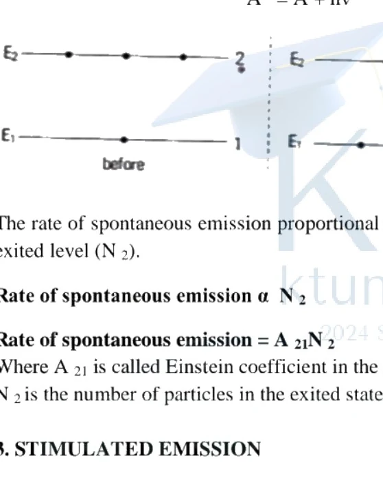
Figure: Spontaneous emission energy level transition diagram
Spontaneous emission energy level transition diagram showing energy levels E2 and E1. On the left under 'before', energy level E2 has a particle represented by a dot, and E1 is empty, with a vertical dashed transition line labelled 1. On the right under 'after', E2 is empty and E1 has a particle, with an emitted photon indicated by a wavy arrow labelled 2.
The rate of spontaneous emission is proportional to the number of atoms per unit volume in the excited level ().
Where is called the Einstein coefficient for spontaneous emission, and is the number of particles in the excited state.
3. Stimulated Emission
An atom in the excited state interacts with an external photon of matching energy and makes a transition to the lower level with the emission of a second identical photon. This is called stimulated emission.
The process may be expressed as:
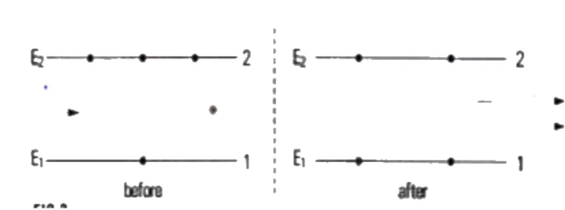
Figure: Diagram showing stimulated emission before and after
Two energy level diagrams comparing the state before and after stimulated emission. Each diagram displays two horizontal energy levels labelled E2 at the top and E1 at the bottom. The left diagram is labelled 'before' showing dots representing particles in the excited state E2 and an incoming/incident action representation. The right diagram is labelled 'after' showing the transition with multiple particle markers and arrows indicating emitted photons moving outward between levels E2 and E1.
The rate of transition to the lower energy level via stimulated emission is directly proportional to the number of atoms per unit volume in the excited level and the energy density of the interacting photon field :
Where is called the Einstein coefficient for stimulated emission, is the number of particles in the excited state, and is the energy density of the interacting photon field. In a laser system, optical amplification takes place primarily due to stimulated emissions.
Comparison Between Spontaneous Emission and Stimulated Emission
| Spontaneous Emission | Stimulated Emission |
|---|---|
| 1. It happens naturally without requiring any external stimulus. | 1. The emission process is triggered or stimulated by an incident photon of matching frequency. |
| 2. Emitted light waves have random phase relationships and lack phase coherence. | 2. Emitted light waves have a definite phase relationship with the stimulating photon and are strictly coherent. |
| 3. Emitted waves propagate in random, omnidirectional patterns. | 3. Emitted light travels in the same direction as the incident photon, ensuring high directionality. |
| 4. Rate of emission is proportional only to the number of atoms in the excited state (). | 4. Rate of emission is proportional to both the energy density of incident radiation and . |
| 5. Light emitted by spontaneous emission is incoherent. | 5. Light emitted by stimulated emission is highly coherent. |
| 6. Conventional light sources (e.g., incandescent bulbs) emit light via spontaneous emission. | 6. Light from a LASER is the direct result of stimulated emission. |
| 7. Photons of slightly different frequencies are generated, resulting in non-monochromatic light. | 7. The spread of photon frequencies is extremely narrow, making the output nearly monochromatic. |
| 8. Net intensity is given by , where is the number of emitting atoms and is photon intensity. | 8. As all photons are in phase, they constructively interfere, producing an intensity . |
| 9. Planes of polarization are oriented randomly; hence, conventional light is unpolarized. | 9. Planes of polarization are identical for all generated photons, yielding polarized laser light. |
Population Inversion, Metastable States, and Pumping
Bridge: Knowing the emission processes, we now examine how to alter thermal equilibrium to achieve population inversion.
The new idea: Metastable states provide longer lifetimes allowing atoms to accumulate for population inversion.
Objectives
- Explain the necessity of population inversion and metastable states.
- Compare different pumping techniques: optical, electrical, chemical, and electron-beam pumping.
- Apply Boltzmann distribution to thermal equilibrium populations.
Concepts to Teach
- Boltzmann distribution: Relates the population of energy levels at thermal equilibrium.
- Metastable state: An excited energy state with an unusually long lifetime.
- Pumping process: The method of exciting atoms from a lower to a higher energy level.
- Optical and electrical pumping: Specific energy transfer mechanisms.
Population Inversion
Under normal thermal equilibrium, the population of atoms in energy levels follows the Boltzmann distribution. Let and be the populations of atoms in the lower energy level and higher energy level respectively. According to Boltzmann's distribution, the ratio is given by:
Where:
- = absolute temperature in Kelvin (\text{K})
- = Boltzmann's constant ()
- = energy difference between the states
Since and temperature , the exponential term is less than 1, meaning . This indicates that the ground state or lower energy level always contains more atoms than the excited state in thermal equilibrium.
However, for light amplification via stimulated emission to dominate, we must achieve population inversion, a non-equilibrium state where the population of the higher energy level exceeds that of the lower energy level ().
Metastable State
Normally, the lifetime of an ordinary excited state is extremely short (on the order of seconds). Atoms spontaneously decay back to the lower level before a sufficient number can accumulate, making population inversion impossible through a simple two-level system.
To sustain population inversion, an energy level with a significantly longer lifetime (typically to seconds)—known as a metastable state—is required. Atoms remain trapped in this excited state long enough to allow a massive accumulation of population inversion when continuously supplied with energy from an external source.
Pumping Process
The method of transferring atoms from a lower energy level to a higher energy level by supplying external energy is called pumping. Various lasers utilize different types of pumping mechanisms depending on their active medium:
- Optical Pumping: Utilizes intense light energy (such as from a flashlamp or another laser) to excite atoms. This is widely used in solid-state lasers like the Ruby laser.
- Electrical Pumping: Uses a high-voltage electric discharge through a gas medium to excite atoms via inelastic electron-atom collisions. This is employed in gas lasers like the He-Ne laser.
- Chemical Pumping: Achieves population inversion directly through the energy released in exothermic chemical reactions.
- Electron Beam Pumping: Involves bombarding a semiconductor chip with a high-energy beam of fast-moving electrons, exciting charge carriers from the valence band to the conduction band. This is used in semiconductor lasers.
Basic Components of a Laser System
Bridge: Having established population inversion requirements, we study how optical cavities sustain stimulated emission.
The new idea: An optical resonator uses feedback mirrors to multiply photons through resonant paths.
1. Active Medium and Core Components
The three basic components of a laser system are the active medium, the pumping agent, and the optical resonator.
Active Medium
An active medium is a medium which, when excited, reaches the state of population inversion and promotes stimulated emissions leading to light amplification. Active mediums are different in different lasers:
- In a ruby laser, ions (Chromium ions) serve as active centers.
- In a laser, atoms serve as active centers.
Pumping Process
For achieving and maintaining the conditions of population inversion, we must continuously raise atoms from the lower energy level to the upper energy level. The pump is an external source that supplies the energy needed to transfer the laser medium into the state of population inversion.
Different pumping techniques are used for different types of lasers:
- Optical Pumping: The method of achieving population inversion using light energy. This method is used in solid-state lasers like the ruby laser.
- Electrical Pumping: The method of achieving population inversion using a sufficiently intense electric discharge in the medium. This is used in lasers.
- Chemical Pumping: Population inversion is achieved by exothermic chemical reactions.
- Electron Beam Pumping: Used in semiconductor lasers. A beam of fast-moving electrons is made to pass through a semiconductor chip, raising electrons in the valence band to the conduction band to produce population inversion.
2. Optical Resonator
In a laser system, an optical resonator produces a highly directional and highly intense laser beam. In an optical resonator, the number of photons is multiplied due to stimulated emission.
Structure of an Optical Resonator: An optical resonator is a cavity consisting of two reflecting mirrors and an active medium. The active medium is placed between the mirrors. One mirror is fully reflecting and the other one is partially reflecting.
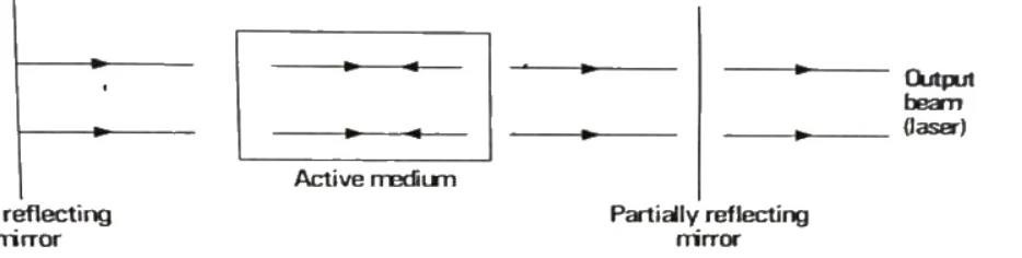
Figure: Laser resonant cavity diagram with fully reflecting mirror, active medium, partially reflecting mirror, and output laser beam.
Laser resonant cavity diagram showing a vertical line on the left representing the 'Fully reflecting mirror' with horizontal arrows pointing right towards a rectangular box labeled 'Active medium' which has horizontal arrows inside representing photons. To the right of the active medium, another vertical line represents the 'Partially reflecting mirror', followed by horizontal arrows extending to the right labeled 'Output beam (laser)'.
Working: We first activate the active medium so that photons are produced due to stimulated emission. Photons get reflected at the two mirrors and travel several times in between them. Finally, the photons are aligned parallel to the axis of the mirrors. Only those photons which are aligned parallel to the axis can escape through the partially reflecting mirror. Amplification of light takes place in the space between two reflecting surfaces called the resonant cavity.
3. Einstein Coefficients and Laser Conditions
Using Einstein coefficients, we can predict the possibility of stimulated emission. The ratio of spontaneous emission to stimulated emission can be calculated using the rate equations:
On simplification and rearranging, the ratio of spontaneous emission to stimulated emission becomes:
In order to make stimulated emission dominant over spontaneous emission, we need:
- Large radiation density : To make large, feedback is provided by placing mirrors to increase radiation density.
- Population inversion (): The number of atoms in the upper excited state must exceed the number in the lower state.
- Small ratio : To realize a small ratio, we choose the excited state to be a metastable state.
The Einstein coefficients play a critical role in calculating quantities like the threshold population required for any laser system.
Ruby Laser and Semiconductor Laser
Bridge: Having learned laser components, we examine practical solid-state and semiconductor laser devices and their diverse applications.
The new idea: Semiconductor lasers achieve population inversion through high forward bias current across a p-n junction.
Objectives: Describe the construction and working of a three-level Ruby laser; Explain the operation of a semiconductor diode laser and its energy band transitions; Calculate threshold currents and emission wavelengths using band gap energy.
Concepts to teach: Ruby rod ( doped with ); Xenon flash tube; Pulsed laser output; Semiconductor laser threshold current ; Band gap .
Ruby Laser
Ruby laser is a solid state laser fabricated by T.H. Maiman in 1960. It operates on a three-level energy scheme.
Construction
The three basic components of a laser system are the active medium, pumping process, and resonant cavity, which are realized in a ruby laser as follows:
- Active Medium: Ruby is a crystalline solid of aluminum oxide () doped with chromium sesquioxide (). The chromium ions () replace some of the aluminum ions (). This gives the transparent crystal a pink or red color depending on the ion concentration. The length of the ruby rod varies from to and its diameter varies from to .
- Pumping Process: Optical pumping is used to excite the chromium ions. The ruby rod is surrounded by a helical quartz tube containing Xenon gas at low pressure. Electrical discharge is maintained inside the tube through a capacitor bank. The flash of the Xenon tube produces optical pumping lasting for several milliseconds. Only a part of this energy is utilized to pump the ions; the remaining energy heats up the apparatus, necessitating an external cooling mechanism.
- Resonant Cavity: The ends of the ruby rod are ground and polished flat, with one end completely silvered (fully reflecting) and the other partially silvered. These parallel ends form an optical resonant cavity.

Figure: Diagram of a Ruby laser setup showing xenon flash tube, ruby rod, fully reflecting and partially reflecting ends, and cooling system.
Diagram of a Ruby laser showing a cylindrical Xenon flash tube wrapped helically around a central Ruby rod. The left end of the ruby rod is labeled 'Fully reflecting' and the right end is labeled 'Partially reflecting'. An outer glass rod or envelope encloses them. A laser beam is shown emerging from the right end. The cooling system connections are indicated with arrows at the bottom. Circuit connections with a capacitor and power source are shown connected to the Xenon flash tube.
Working
Chromium atoms in the ruby absorb green and blue light from the Xenon flash tube.
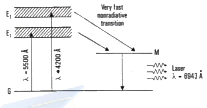
Figure: Energy level diagram of Ruby Laser
Energy level diagram of Ruby Laser showing ground state G at the bottom, excited energy bands E1 and E2 represented with hatched regions, and a metastable state M above G. Vertical upward arrows originate from G pointing to E2 (labelled lambda = 4200 Angstrom) and to E1 (labelled lambda = 5500 Angstrom). A diagonal arrow points from E1 to M with the text 'Very fast nonradiative transition'. A horizontal transition arrow goes from M down to G with wavy lines indicating laser emission, labelled 'Laser lambda = 6943 Angstrom'.
- Upon absorbing optical energy, the chromium ions are raised from the ground state to broad excited energy bands and .
- The ions residing in bands and possess a very short lifetime. They undergo fast, non-radiative transitions down to a metastable state , which has a much longer lifetime (approximately ). Due to this long lifetime, atoms accumulate in state , establishing a population inversion between the metastable state and the ground state .
- Once population inversion is achieved, lasing action is triggered by spontaneously emitted photons, causing stimulated emission that brings atoms back to the ground state.
- Pumping is continuously re-established to maintain pulsed laser output. The duration of each optical pulse is about a microsecond, producing a high-intensity, monochromatic beam that emerges through the partially reflecting surface.
Semiconductor Laser
Construction
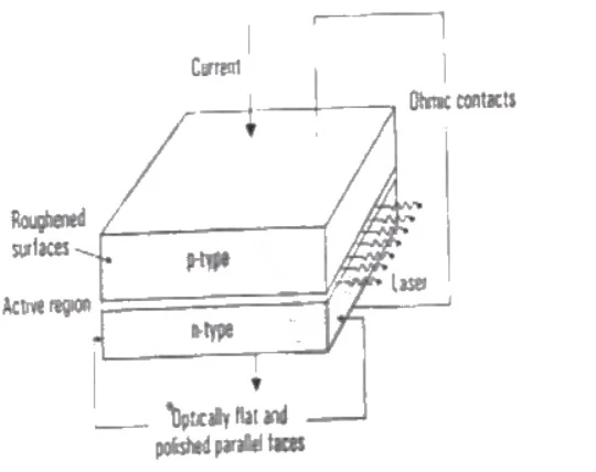
Figure: Construction of a semiconductor laser diode
3D schematic diagram of a semiconductor laser diode showing p-type and n-type layers, an active region, roughened surfaces on the sides, optically flat and polished parallel faces at the front and rear emitting a laser beam, and ohmic contacts at the top and bottom with vertical arrows indicating Current.
Semiconductor laser diodes are extremely small in size, with side dimensions on the order of . The p-n junction lies in the horizontal plane through the center. The top and bottom faces are metallized to provide ohmic contacts for passing current through the diode. The front and rear faces are polished parallel to each other and perpendicular to the junction to act as the resonant cavity. The other two opposite faces are roughened to suppress transverse lasing. The active region consists of an ultrathin layer of about thickness.
Working and Population Inversion
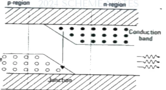
Figure: Energy band diagram of a semiconductor laser under forward bias
Energy band diagram of a semiconductor laser under forward bias, showing p-region and n-region separated by a junction. The conduction band at the top contains electrons (represented as dots) and the valence band at the bottom contains holes (represented as circles). Wavy arrows on the right indicate photon emission.
In a semiconductor laser, population inversion is achieved when more energy states are occupied by carriers in the conduction band than in the valence band. Under high forward bias, electrons are injected from the n-side into the p-side, and holes are injected from the p-side into the n-side.
- Spontaneous Emission: At low forward bias currents, injected electrons and holes recombine across the junction, causing spontaneous emission. The device functions primarily as a Light Emitting Diode (LED).
- Stimulated Emission: At high forward bias currents, stimulated emission becomes dominant, and the device functions as a laser. The threshold for this transition is characterized by the threshold current density , which is approximately for Gallium Arsenide () diodes at room temperature.
Mathematical Formulation
The minimum wavelength of radiation emitted by a semiconductor laser having a band gap energy is given by:
Where:
- is the band gap energy (in Joules or electron-volts)
- is Planck's constant ()
- is the frequency of emitted radiation (in )
- is the speed of light in vacuum ()
- is the emission wavelength (in meters)
Advantages of Semiconductor Lasers
- Extremely compact size.
- Direct electrical pumping via low-power currents (approx. at ).- High electrical-to-optical conversion efficiency exceeding .
- Direct high-frequency modulation capability in the gigahertz range, making them ideal for optical fiber communication.
- Easy integration with microwave oscillators, optical components, and integrated circuits.
Comparative Analysis
Difference Between Ordinary Light and Laser Light
| Laser Light | Ordinary Light |
|---|---|
| 1. Angular spread is extremely small. | 1. Angular spread is large. |
| 2. Highly directional. | 2. Non-directional (divergent). |
| 3. Highly intense. | 3. Less intense. |
| 4. Coherent and in-phase. | 4. Incoherent and out-of-phase. |
| 5. Highly monochromatic. | 5. Polychromatic. |
| 6. Examples: He-Ne laser, Ruby laser. | 6. Examples: Sunlight, Sodium vapor lamp. |
Difference Between LED and Laser Diode
| LED | Semiconductor Laser |
|---|---|
| 1. Governed by spontaneous emission. | 1. Governed by stimulated emission. |
| 2. Junction facets do not need to be polished. | 2. Facets must be polished parallel to form a resonator. |
| 3. Low optical power output. | 3. High optical power output. |
| 4. Lower luminous intensity. | 4. Very high spatial and temporal intensity. |
| 5. Requires low current density. | 5. Requires high threshold current density (). |
Applications of Lasers
1. Applied Science and Engineering
- Medical Applications: Utilized as precision surgical knives for bloodless and painless operations, ophthalmological procedures (e.g., treatment of detached retinas, cataracts, and glaucoma using pulses), and physical therapy.
- Microelectronic Applications: Used for precise trimming of integrated circuit components and microelectronic fabrication using pulsed Nd:YAG lasers.
- Industrial Processing: Applied in high-speed hole drilling (pulse durations to , power densities to ), precision laser cutting of metals and ceramics, and contactless laser welding in normal atmospheres without chemical contamination or mechanical distortion.
- Material Heat Treatment: Surface hardening of automobile engine parts (e.g., cylinder blocks, gears) through localized heating and rapid cooling.
2. Pure Science
- Physics: Investigation of non-linear optical phenomena and high-resolution laser spectroscopy.
- Chemistry: Selective excitation of specific atoms and molecules using tunable lasers to control chemical reaction pathways and study kinetics.
- Biology: Targeted destruction of specific cellular structures and analysis of fast biochemical processes using ultrashort laser pulses.
Principles and Structure of Optical Fibers
Transitioning from laser light sources, we investigate how light is guided over long distances using optical fibers. Light is guided through an optical fiber via repeated total internal reflections at the core-cladding boundary.
Principle of Total Internal Reflection (TIR)
The fundamental principle underlying optical fiber communication is Total Internal Reflection. If the angle of incidence in the denser medium is greater than the critical angle , the incident ray is reflected back into the same medium completely.

Figure: Diagram illustrating Total Internal Reflection in an optical fiber with denser medium n1 and rarer medium n2, showing critical angle theta_c and angles greater than theta_c.
Ray diagram illustrating total internal reflection with two horizontal regions: a top rarer medium with refractive index n2 and a bottom denser medium with refractive index n1. Rays originate at the boundary and travel from the denser to the rarer medium. Three points A, B, and C are marked along the interface from left to right. At point A, the angle of incidence equals the critical angle theta_c and the ray refracts along the boundary. At point B, the angle of incidence equals theta_c and the ray reflects entirely within the denser medium. At point C, the angle of incidence is greater than theta_c, marked as >theta_c, and the ray reflects completely back into the denser medium.
The conditions required for total internal reflection are:
- Light must travel from an optically denser medium (refractive index ) to a rarer medium (refractive index ).
- The angle of incidence in the denser medium must be greater than the critical angle .
Structure of an Optical Fiber
An optical fiber is a cylindrical dielectric waveguide consisting of three concentric coaxial regions:
Figure: Diagram showing the structure of an optical fiber consisting of Core, Cladding, and Protective plastic coating.
Cylindrical layered structure diagram representing an optical fiber. The innermost concentric cylinder is pointed to by a label 'Core'. The middle cylindrical layer is labelled 'Cladding'. The outermost cylindrical layer is labelled 'Protective plastic coating'.
i) Core: The innermost cylindrical region of the optical fiber through which light propagates. It is typically made of high-purity glass or plastic with a refractive index of .
im) Cladding: The middle coaxial layer surrounding the core, made of glass or plastic with a lower refractive index (where ). Total internal reflection takes place at the core-cladding interface, trapping light inside the core.
iii) Protective Coating (Buffer Coating): The outermost polymer or plastic layer that protects the glass fiber from mechanical stress, moisture, and physical damage.
Classification and Comparison of Optical Fibers
Optical fibers are broadly classified based on the refractive index profile of the core and the number of optical modes they support:
- Step-index single-mode fiber
- Step-index multimode fiber
- Graded-index multimode fiber
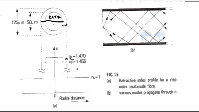
Figure: Step index fibre profile and propagation modes
FIG. 15: Step index multimode fibre. Sub-figure (a) shows the fiber cross-section with core diameter 50 micrometers and cladding diameter 125 micrometers, and a step-like refractive index profile graph with n1 = 1.470, n2 = 1.455, and radial distance on the horizontal axis. Sub-figure (b) shows various modes propagating through the step index multimode fiber in zigzag paths.
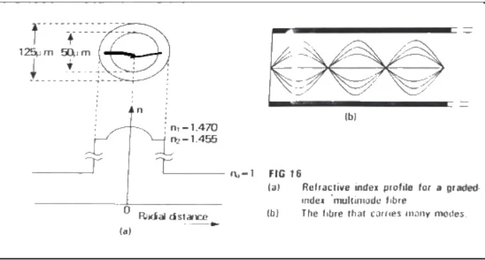
Figure: Graded index fibre profile and propagation modes
FIG. 16: Graded index multimode fibre. Sub-figure (a) shows the fiber cross-section with core diameter 50 micrometers and cladding diameter 125 micrometers, and a parabolic refractive index profile graph with n1 = 1.470, n2 = 1.455, and radial distance on the horizontal axis. Sub-figure (b) shows sinusoidal light ray paths propagating through the graded index multimode fibre.
| Step Index Fiber | Graded Index Fiber |
|---|---|
| 1. The refractive index changes abruptly at core to cladding boundary. | 1. The refractive index decreases radially outwards from core to cladding. |
| 2. The diameter of the core is about and cladding is for multimode; core is about and cladding is for single-mode. | 2. The diameter of the core is about and that of cladding is for multimode graded index. |
| 3. Attenuation is more for multimode step index, but very low for single-mode step index. | 3. Attenuation is low. |
| 4. Numerical aperture is higher for multimode step index and very low for single-mode step index. | 4. Numerical aperture is lower compared to step index fibers. |
| 5. Refractive index profile is step-like. | 5. Refractive index profile is parabolic. |
| 6. Bandwidth-distance product is less than for multimode step index. | 6. Bandwidth-distance product is very large, between and . |
| 7. Single-mode step index fibers are widely used for long-distance terrestrial transmissions. | 7. Widely used for telephone loop distribution systems. |
| 8. Coupling of single-mode fiber is difficult; multi-mode step index is easier to couple. | 8. Coupling fiber to light sources is more difficult. |
Fiber Optic Communication and Numerical Aperture Derivations
Bridge: Having examined fiber structures, we now analyze their light-gathering mathematical limits and system communication blocks.
The new idea: Numerical aperture quantifies the light gathering capacity of an optical fiber based on core and cladding refractive indices.
Single Mode vs. Multimode Fiber Comparison
| Single Mode Fiber | Multimode Fiber |
|---|---|
| 1.) Only one mode of light signal can propagate through the fiber. | 1.) Multimode fiber allows a large number of modes for the light rays travelling through it. |
| 2.) Smaller core diameter. | 2.) It has a larger core diameter. |
| 3.) The difference of refractive indices of core and cladding is very small. | 3.) The difference in refractive indices is larger than the single mode fiber. |
| 4.) No multimodal dispersion. | 4.) There is a multimodal dispersion. |
Fiber Optic Communication System Block Diagram
Communication systems that carry information through a guided optical fibre cable are called fibre optic communication systems. The information carrying capacity of a communication system is directly proportional to its bandwidth. The major components of an optical communication system are an Optical Transmitter, Optical Fibre transmission line, and Optical Receiver.
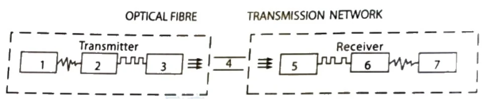
Figure: Block diagram of an optical communication system
Block diagram of an optical communication system showing a Transmitter section enclosed in a dashed box containing blocks numbered 1, 2, and 3 connected in sequence; a middle section representing the OPTICAL FIBRE / TRANSMISSION NETWORK containing block 4; and a Receiver section enclosed in a dashed box containing blocks 5, 6, and 7 connected in sequence. The blocks are labelled below as: 1. Subscriber's Telephone, 2. Encoder, 3. Optical Transmitter, 4. Optical Fibre link, 5. semiconductor photo detector, 6. Decoder, 7. Subscriber's Telephone.
- Unit 1: Subscriber's telephone where sound wave is converted into corresponding electrical signal.
- Unit 2: Encoder, which converts continuous electric signal into coded digital pulse by means of an analogue-to-digital converter.
- Unit 3: Optical transmitter, which usually consists of a semiconductor laser or LED. The diode turns ON and OFF according to the bit stream to be sent, and thus the light source is modulated.
- Unit 4: Optical fibre transmission link.
- Unit 5: Semiconductor photo detector at the receiving end which converts the optical signal back into electrical pulses.
- Unit 6: Decoder, which converts digital pulses into analogue signal with the help of a digital-to-analogue converter.
- Unit 7: Subscriber's telephone where sound is reproduced.
Numerical Aperture and Acceptance Angle
The Numerical Aperture (NA) of a fiber is the measure of the light gathering capacity of the fiber. Quantitatively, NA is the measure of the angle over which light is accepted in the fibre and is proportional to the sine of the fiber acceptance angle.
Where is the refractive index of the core, is the refractive index of the cladding, and represents the acceptance angle.
Acceptance Angle: The minimum angle of incidence at the end face of a fibre for which light ray can propagate through it is called the acceptance angle for the fibre.
Derivation of Numerical Aperture and Acceptance Angle
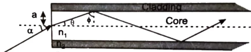
Figure: Ray propagation in a step-index optical fiber
Ray propagation diagram for a step-index optical fiber. Shows a central core of refractive index n1 and diameter/region labeled 'Core', surrounded by cladding labeled 'Cladding' of refractive index n2, situated in an external medium of refractive index n0. A dashed horizontal center axis runs along the length of the core. An incoming ray from the lower-left enters the core face at an angle of incidence alpha with respect to the normal/axis, refracts at an angle theta to the axis, and travels to strike the core-cladding interface at an angle phi to the normal, where it undergoes total internal reflection and continues forward inside the core.
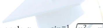
Figure: Optical fiber acceptance angle illustration
Optical fiber acceptance angle illustration showing light rays entering an optical fiber core with acceptance angle alpha_m. The core has refractive index n1, cladding has n2, and surrounding medium has n0.
Consider a step index fibre made of a core of refractive index and cladding of refractive index (). The end faces of the fibre are cut at right angles to the axis of the fibre. A ray of light enters through one end from air into the core at an acceptance angle . After refraction, the ray is incident at the core-cladding interface at an angle , which is greater than the critical angle . Hence, it undergoes total internal reflection.
Theory: Refractive index of core with respect to air ():
From the geometry of the figure, . Substituting into equation (1):
For critical rays, , (critical angle):
The refractive index of core with respect to cladding is:
Using the trigonometric identity :
Substituting equation (4) and (refractive index of air) into equation (2):
Advantages of Optical Fibers Over Ordinary Cables
- Light weight, small size, and flexibility allow easy handling.
- No hazards of short circuit compared to copper cables.
- Very low attenuation at optimum wavelengths.
- Immune to cross-talk between cables caused by magnetic induction.
- Safer and easier to install and maintain.
- Very high bandwidth and immense information carrying capacity.
Applications of Optical Fibers
- General: Defence communication systems (controlling ships, aircraft, missiles), space communication, smoke/pollution detectors, non-destructive testing, security alarms, cable TV, LAN, WAN, and internet infrastructure.
- Medical: Endoscopy for internal visualization, detecting tissue abnormalities, ophthalmological retinal reattachment, laser vaporization of arterial plaque, and biosensing (temperature, blood pressure, oxygen saturation).
Solved Numerical Problems
Problem 1
Calculate the numerical aperture (NA), fiber acceptance angle, critical angle, and angle of refraction of an optical fiber having core index and cladding index respectively.
- Given: Core index , Cladding index
- Find: , , ,
- Formula & Substitution:
- Calculations & Answers:
Problem 2
A fiber cable has an acceptance angle of and a core refractive index of . Calculate the refractive index of the cladding.
- Given: ,
- Find:
- Formula & Substitution:
- Final Answer:
Problem 3
Calculate the numerical aperture (NA), fiber acceptance angle, critical angle, and angle of refraction of optical fiber having core index and cladding index respectively.
- Given: ,
- Find: , , ,
- Formula & Substitution:
- Calculations & Answers: